Biomedical Engineering Reference
In-Depth Information
Detection site 2
Detection site 1
Sample 1
Sample 1
Te st
stimuli
droplet
2 × 3 array
mixer
Droplet
source
Droplet
sink
Reagent 1
Reagent 2
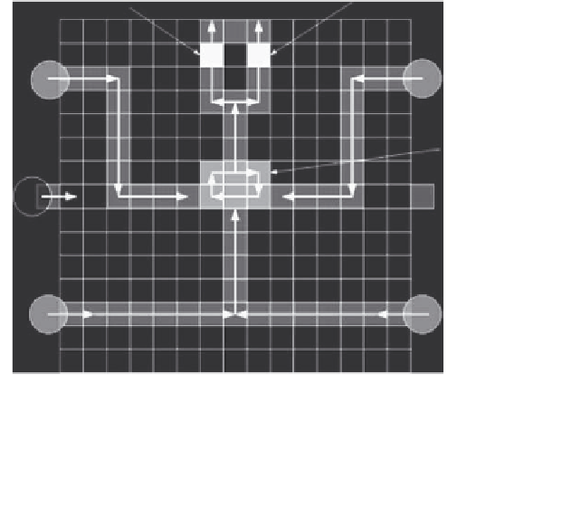
Figure 3.11
A 15 × 15 array used for multiplexed bioassays.
TAble 3.2
Bioassay Sch
edule for a Full-Addressable Array
Step/Time
Elapsed (s)
Operation
Step 1/0
Sample 2 and reagent 2 start to move toward the mixer.
Step 2/0.8
Sample 2 and reagent 2 begin to mix together and turn around in the 2 × 3 array
mixer.
Step 3/6.0
Sample 1 and reagent 1 start to move toward the mixer.
Sample 2 and reagent 2 continue the mixing.
Step 4/6.8
Sample 2 and reagent 2 finish the mixing, and product 2 leaves the mixer to
optical detection location 2. Sample 1 and reagent 1 begin to mix in the
2 × 3 array mixer.
Step 5/12.8
Sample 1 and reagent 1 finish the mixing, and product 1 leaves the mixer to the
optical detection location 1. Product 2 continues the absorbance detection.
Step 6/19.8
Product 2 finishes optical detection and leaves the array to the waste reservoir.
Product 1 continues the absorbance detection.
Step 7/25.8
Product 1 finishes optical detection and leaves the array to the waste reservoir.
One procedure of the multiplexed bioassays ends.
array, as shown in Figure 3.11. The schedule for the set of bioassays, if a
microfluidic array with 225 control pins is available, is listed in Table 3.2; one
iteration of the multiplexed assays takes 25.8 s [38]. The movement of drop-
lets is controlled using a 50 V actuation voltage with a switching frequency
of 16 Hz. A depiction of the droplet paths for multiplexed glucose and lactase
assays is shown in Figure 3.11.