Biomedical Engineering Reference
In-Depth Information
450
Routing-oblivious synthesis
Routing-aware synthesis
400
350
300
250
200
150
100
110
120
130
140
Array Size (number of electrodes)
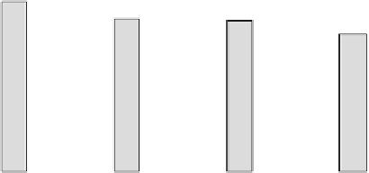
Figure 2.9
Assay completion times (with droplet transportation time included) for [15] and for the pro-
posed routing-aware synthesis method.
Defective cells
To p glass plate
400
T
300
200
100
0
Bottom
10
10
X
5
Y
5
0
0
(a)
(b)
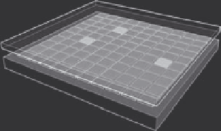
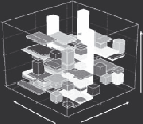
Figure 2.10
(a) A defective 10 × 10 microfluidic array; (b) reconfiguration results for postsynthesis defect
tolerance.
that one optical detector is rendered defective after manufacturing. Thus, the
operations assigned to this detector have to be remapped to other detectors.
The modified synthesis method proposed in Section 2.3.1 is used here to carry
out the reconfiguration so that these manufacturing defects are tolerated. The
reconfiguration results are shown in Figure 2.10b. This new design allows the
protein assay to operate on this defective biochip with an increase of only 7%
in the completion time; that is, the completion time is now 387 s.
2.4.3 results for Presynthesis Defect Tolerance
We next evaluate the presynthesis defect tolerance that is achieved for
the protein assay using the enhanced routing-aware method described
in Section 2.3.2. We first use this method to find a desirable solution that