Biomedical Engineering Reference
In-Depth Information
Detection sites
Sample 2
Sample 1
2×2-array
mixer
Storage units
2
Reagent 1
Reagent 2
1
2
3
4
5
1
4-Electrode linear
array (as dilutor/mixer)
Segregation cells
(a)
(b)
4
1
35296810
7
3
524
1810 796
2
413
5796810
1
352
468107 9
52413107 968
14 11 13 15
12 19 16 18 20 17
13 15 12 14 11 18 20 17 19 16
12 14 11 13 15 17 19 16 18 20
11 13 15 12 14 16 18 20 17 19
15 12 14 11 13 20 17 19 16 18
:Partition 1 (pins 1-5)
:Partition 3 (pins 11-15)
:Partition 2 (pins 6-10)
:Partition 4 (pins 16-20)
(c)
(d)
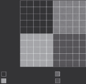
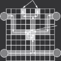
Figure 4.43
Pin-constrained chip designs for functional test evaluation: (a) a linear 5-phase-bus chip for dilu-
tion; (b) layout and droplet routes for the multiplexed-assay chip; (c) an array-partitioning-based
array for a multiplexed assay; and (d) a cross-referencing-based array for a multiplexed assay.
chip design for the multiplexed assay. The chip is divided into four partitions,
and each partition is controlled using a dedicated set of pins. Figure 4.43d
shows a cross-referencing-based chip design for the same assay. The simple
design prototype is composed of 10 row pins and 10 column pins. Finally, for
the broadcast-address method, the design shown in Figure 4.38 is used. The
chip is designed for executing on-chip PCR reactions.
Next, we apply the extended functional test method proposed in Subsection
4.5.4 to these pin-constrained chips. The number of droplet manipulation
steps are recorded and shown in Figure 4.44. This figure also presents the
number of manipulation steps required by the functional test, assuming the
chip is direct addressable. The functional test on a cross-referencing-based
chip requires the same test time as on a direct-addressable chip. For other
pin-constrained designs, the functional test can still be carried out effectively,
though with an increase in test application time. Considering the significant
reduction in the number of control pins, such a compromise is acceptable.