Biomedical Engineering Reference
In-Depth Information
Next, we propose efficient functional test methods to detect the defects and
malfunctions listed in Table 4.2. The dispensing test, mixing test, splitting
test, and capacitive sensing test are developed to address the corresponding
malfunctions. A routing test procedure is used to detect all physical defects.
4.5.1 Dispensing Test
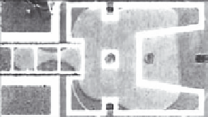
The dispensing test targets the malfunctioning of the dispensing opera-
tion. Figure 4.25 provides a comparison between normal dispensing and
an example of dispensing failure. As shown in Figure 4.25b, the dispensed
droplet in a malfunctioning scenario cannot be detached from the drop-
let in the reservoir. Therefore, when we move the dispensed droplet away
from the reservoir, an additional droplet from the reservoir is extracted and
moved as well. In this case, the dispensed “droplet” can be several times
larger than the normal size, which may result in the catastrophic failure of a
volume-sensitive bioassay.
Here we propose a test method based on capacitive sensing to detect
these dispensing failures. The circuit diagram for fault detection is shown
in Figure 4.2. It has been shown in the literature that dispensing involves
a reservoir and the three electrodes closest to it [67]. We therefore define
every reservoir together with its three neighboring electrodes as a
dispensing
cluster
. The third electrode in the cluster, that is, the electrode farthest from
the reservoir, is connected to a capacitive sensing circuit for test readout
(see
Figure 4.26)
. When the test starts, a droplet is dispensed from the reservoir
until it reaches the third electrode. We expect a positive pulse with a normal
amplitude for both fault-free dispensing and dispensing failure. Next, we
route the dispensed droplet one electrode in the forward direction. During
correct dispensing, the fully dispensed droplet moves completely to the
fourth electrode; therefore, no pulse is detected by the capacitive sensing
circuit output at this time. However, if the droplet undergoes a dispensing
failure and it is still connected to the liquid in the reservoir, there must be
Dispensed droplet
Dispensing failure
Reservoir
Reservoir
(a)
(b)
Figure 4.25
Illustration of (a) normal dispensing and (b) dispensing failure, for a fabricated microfluidic
biochip.