Hardware Reference
In-Depth Information
outAvailable[0...N-1]
outAvailable[0]
arb
#0
outPort
ready output[0...N-1]
dst
en
1
head
1
en
outLock
ready
valid
outAvailable[N-1]
arb
#
N-1
granted
data
Input #0
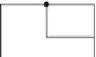
Fig. 3.11
The organization of the request generation and grant handling logic per input port that
incorporates also flow control handshake and the necessary input and output state variables
access to
outPort
Œi . Recall that
outPort
Œi is a N -bit vector following the one hot
code. If the j th bit of
outPort
Œi is asserted, it means that the packet from the i th
input should connect to the j th output port of the switch. Also, each output holds
one state variable called
outAvailable
Œj (corresponds to the j th output) that denotes
if it is free or if it has been allocated to a selected input port. In all cases, the per-
input and per-output variables are set by the head flits and released by the tail flits
of a packet.
The details of the request generation and grant handling logic attached to each
input (or else called the input controller) is shown in Fig.
3.11
. Each input receives
N
outAvailable
bits (one per output) and N ready signals that declare buffer
availability in the specific clock cycle. The flits of the packet select the
outAvailable
and ready signals that correspond to their destined output port. In the case of head
flits this information comes directly from the bits of the packet (dst field) while in
the case of body and tail flits comes from the stored
outPort
Œi variable. For the
head flits, the valid bit of each source is masked with the selected availability flag.
If the output is available the valid bit will remain active. If the output is taken it will
be nullified. This qualified valid bit then should check for buffer availability at the
selected output port. Therefore, it is again masked with the selected ready signal
to produce the request sent to the output arbiters. If the selected output buffer is
available, the corresponding head flit can try to gain access to the selected output
port. The masked input requests should be distributed to the appropriate output
arbiter. As shown in Fig.
3.11
, this is done by an input demultiplexer that transfers
the qualified valid bits to the appropriate output. From each input, N request lines
connect to the outputs where only one of them is active.
The grants produced by the output arbiters are reshuffled and gathered per input.
The OR gate, depicted in Fig.
3.11
, merges the grant bits to one grant bit that is


Search WWH ::

Custom Search