Hardware Reference
In-Depth Information
Inputs
Many to one
connection
outAvailable
arb
Output
outAvailable
head
ready output
outAvailable
Switching
module
req
en
arb
outLock
ready
valid
data
grant
dequeue
MUX
sel
Link
ready
valid
data
from/to other
inputs
Input #0
Output Buffer
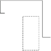
Fig. 3.2
The organization of a many-to-one connection including the necessary output and input
state variables as well as the request generation and grant handling logic that merges switching
operations with link-level flow control
Each input wants to send a packet that contains one head flit, a number of body
flits and a tail flit that declares the end of the packet. Since each flit should travel
on the shared link as an atomic entity the link should be allocated to the packet as a
whole: The head flit will arbitrate with the head flits of the other inputs and once it
wins it will lock the access to the output. This lock will be released only by the tail
flit of the packet. Therefore, an output state variable is needed, called
outAvailable
,
that declares the output's availability to connect to a new input. The same state bit
exists also at each input and called
outLock
.When
outLock
Œi
D
1 means that the
i th input has been connected to the output. Following Fig.
3.2
,the
outAvailable
flag
is placed at the output of the switching module (arbiter and multiplexer). This is
the most reasonable placement since the
outAvailable
state bit is not a characteristic
variable of the output buffer (or the receiver in general) but a variable needed to
guide the arbitration decisions taken locally by the switching module at the sender's
side.
Each input needs to declare its availability to connect to the output. This is done
via the valid bits of the input buffers. For the head flits, as shown in Fig.
3.2
, the valid
bits are first qualified with the
outAvailable
state bit. If the output is not available, all
valid bits will be nullified or kept alive in the opposite case. Before transferring the
qualified valid bits to the arbiter we need also to guarantee that there is at least one
free buffer slot at the sink. Therefore, the qualified valid bits are masked with the
ready signal of the output that declares buffer availability. After those two masking
steps the valid signals from each input act as requests to the arbiter that will grant
only one of them. Once the arbiter finishes its operation it returns a set of grant wires
that play a triple role.
They drive the select signals of the output multiplexer that will switch to the
output the flit of the selected input.


Search WWH ::

Custom Search