Hardware Reference
In-Depth Information
Link
width
Head
Body
flit ID
sourceID
destinationID
packetNO
Body
Tail
flit flow control
data
valid
ready
isHead
isTail
sender
receiver
packet framing
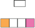
Fig. 2.19
The organization of packets and the additional signals added in the channel
to
distinguish the type of each arriving flit
link 1
link 2
link 3
HBBT
link 1
HBBT
link 2
HBBT
link 3
01 2345
Fig. 2.20
The pipelined flow of the flits of three consecutives packets crossing the links between
three nodes
each link follows the rules of the selected flow control policy independently per
link. Therefore, the buffers at the end of each link should provide the necessary
space for accommodating all incoming flits and offer full transmission throughput.
Store-and-forward required the entire packet to reach each node before initiating
next transmission for the next node.
The requirement of storing and not dropping the incoming flits to intermediate
nodes raises the following question. How much free buffering should be guaranteed
before sending the first word of a packet to the next node? The answer to this
question has two directions. Virtual Cut Through (VCT) requires that the available
downstream buffer slots to be equal to the number of flits of the packet (Kermani
and Kleinrock
1979
). With this technique, each blocked packet stays together and
consumes the buffers of only one node since there is always enough room to fit the
whole packet. On the contrary, wormhole (WH) removes this limitation and each
node can host only a few flits of the packet (Dally and Seitz
1986
). Then, inevitably,
in the case of a downstream blocking, the flits of the packet will be spread out in the


Search WWH ::

Custom Search