Hardware Reference
In-Depth Information
a
b
1
2
3
4
5
6
data
clock
valid
valid
data
word1
word2
word3
ready
ready
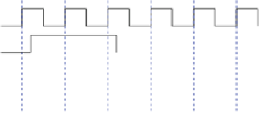
Fig. 2.1
(
a
) A flow-controlled channel with ready/valid handshake and (
b
) an example of
transferring of three words between the sender and the receiver
Figure
2.1
b shows an example of data transfers between a sender and a receiver
on a flow-controlled link. In cycle 2, the sender has a valid word on its output
(word1), but the receiver cannot accept it. The channel is in wait state. In cycle
3, data transfer actually happens since the sender and the receiver independently
observe the channel's valid and ready signals being true. In cycle 4, the channel is
in idle state since the receiver is ready but sender does not offer valid data. Channel
state changes in cycle 5, where the receiver is ready and word2 is immediately
transferred. The same happens in the next cycle. The sender is not obliged to wait
for the ready signal to be asserted before asserting the valid signal. However, once
valid data are on the link they should not change until the handshake occurs.
In this example, and in the rest of the topic we assume that data transfer occurs
at the edges of the clock and all communicating modules belong to the same clock
domain, which is a reasonable assumption and holds for the majority of the cases.
When the sender and the receiver belong to different clock domains, some form
of synchronization needs to take place before the receiver actually receives the
transmitted word. A concrete description synchronization-related issues can be
found in Ginosar (
2011
).
2.1
Elastic Buffers
The ready/valid handshake allows the sender and the receiver to stop their operation
for an arbitrary amount of time. Therefore, some form of buffering should be
implemented in both sides to keep the available data that cannot be consumed during
a stall in either side of the link.
The elastic buffer is the most primitive form of a register (or buffer) that
implements the ready/valid handshake protocol. Elastic buffers can be attached to
the sender and the receiver as shown in Fig.
2.2
. The EB at the sender implements
a dual interface; it accepts (enqueues) new data from its internal logic and transfers
(dequeues) the available data to the link, when the valid and ready signal are both
equal to 1. The same holds for the EB at the receiver that enqueues new valid data
when it is ready and drains the stored words to its internal logic (Butts et al.
2007
).


Search WWH ::

Custom Search