Hardware Reference
In-Depth Information
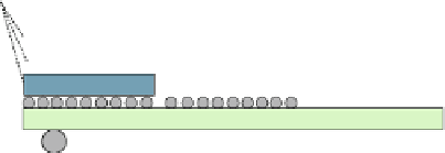
m10
m9
metal
layers
m8
m7
m6
m5
m4
m2
m3
m1
transistors
silicon
Fig. 1.1
The transistor and the metal layers of an integrated circuit
3D Stacked Chips
Through-Silicon VIAs
Silicon Interposer
for 2.5D integration
Fig. 1.2
2.5D and 3D integration possibilities for large SoCs
with larger cross sections, that offer lower resistance, and allow transferring bits
in longer distance with lower delay. Due to manufacturing limitations upper metal
layers should be placed further apart and should have a larger minimum width
thus limiting the designer to use less wires per connection bus. Still, the wires that
belong to the upper metal layers can be a very useful resource since they allow
crossing several mms of on-chip distance very fast (Golander et al.
2011
; Passas
et al.
2010
). In every case, using wisely the density of the upper and the lower
metal layers allows for the design of high-bandwidth connections between any two
components (Ho et al.
2001
).
Technology improvement provides the designer with more connectivity. For
example 2.5D integration offers additional across-chip wires with good charac-
teristics allowing fast connections within the same package using the vertical
through-silicon vias of a silicon interposer (Maxfield
2012
) as depicted in Fig.
1.2
.
On the other hand, 3D integration promises even more dense connectivity by
allowing vertical connections across different chips that are stacked on top of
each other offering multiple layers of transistor and metal connections. Instead
of allowing stacked chips to communicate using wired connections, short-distance
wireless connectivity can be used instead, using, either inductive, or capacitive data
transfer across chips (Take et al.
2014
). Finally, instead of providing more wiring


Search WWH ::

Custom Search