Hardware Reference
In-Depth Information
0
1
2
3
4
5
6
7
8
cc
H
LT-BW
RC-VA
SA-DQ
LT-BW
ST
su
cc
ST
B
LT-BW
SA-DQ
LT-BW
cc
ST
T
LT-BW
SA-DQ
LT-BW
cc
ST
H
LT-BW
RC-V
su
SA-DQ
LT-BW
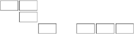
Fig. 9.16
An example of the operation of the 3-stage pipelined router RC-VA|SA|ST for the flits
of two packets arriving back-to-back at same input VC
register, after crossing the corresponding per-input multiplexer. In the meantime, the
body flit remains in the input VC buffer waiting its turn. In cycle 3, as the head flit
traverses the crossbar and consumes a credit, the body flit performs SA and advances
towards the data pipeline register at the input of the crossbar.
In cycle 4, while the head flit is crossing the link moving to the next router, the
body flit leaves the intermediate pipeline register and moves to the selected output,
and the tail flit performs SA. The head flit of the following packet that arrives in the
same input VC remains in the buffer until it reaches the frontmost position of the
input VC buffer. Once the tail flit of the first packet is dequeued at the end of cycle
4, the head flit of the second packet performs RC and VA in cycle 5. If the second
packet arrived at a different input VC then it could have completed RC and VA one
cycle earlier, e.g., in cycle 4.
9.5.3
Four-Stage Pipelined Organization: RC|VA|SA|ST
The 4-stage pipelined organization of the router executes each task involved in a VC-
based router in a different pipeline stage. The implementation of this organization
is illustrated in Fig.
9.17
. For the separation of RC and VA, an intermediate EB
is put in front of the input VC buffer, while all per-input VC state variables are
turned to pipeline registers after removing any bypass connection. The dequeued
flits are registered in the data path prior to entering the crossbar, as required by
the SA pipeline stage, while the input VC buffers are augmented with more buffer
slots in order to support the increased round trip time imposed by the delayed credit
consumption (CC occurs in the last pipeline stage).
An example of the router's cycle-by-cycle behavior is shown in Fig.
9.18
.The
first head flit arrives at an input VC of the router in cycle 0. Then, in cycle 1, in
parallel to the arrival of the body flit of the same packet, the head flit executes RC
and moves to the intermediate EB of the input VC. In cycle 1, the head flit allocates
an output VC, that is stored it in corresponding
outVC
register. In cycle 2, the head
flit having allocated an output VC, participates in SA and wins in the same cycle.
The received grant causes the head flit to dequeue from the intermediate EB and


Search WWH ::

Custom Search