Hardware Reference
In-Depth Information
The request is granted in the same cycle, which allows the head flit to cross the
output multiplexer (ST) and consume an output VC credit. In the meantime, the tail
flit arrives, and the body flit remains idle at the input VC buffer, blocked by the head
flit that currently occupies the frontmost position of the input VC buffer.
In cycle 3, while the head flit crosses the link (LT), moving towards the next
router, the body flit performs SA. Once granted, it leaves the input VC buffer and the
frontmost position of the same input VC buffer is taken by the tail flit that follows.
The tail flit succeeds in cycle 4 in SA and it is written to the output pipeline register,
after releasing the availability of the allocated output VC. The head flit of the second
packet that arrived in cycle 3 for the same input VC, manages to appear at the
frontmost position of the input VC buffer in cycle 5; in this cycle, all input VC
state variables are already reset by the previously departed tail flit. The head flit
must first acquire an output VC, after performing RC and VA, and use the allocated
output VC in the next cycle, following the same procedure as the head flit of the
previous packet.
In this configuration, an input VC remains idle for a cycle between two
consecutive packets, i.e., a bubble appears in the flit flow after a tail flit departs.
This only affects packets arriving contiguously for a single input VC, or packets
that are heading to the same output VC, irrespective of the input VC they belong to.
9.3.2
Example 2: Two Packets Arriving at Different Input VCs
In this example, illustrated in Fig.
9.10
, we consider two packets arriving in the
same input but interleaved on two VCs. We assume that the arriving packets are
free to change VC, when they leave the current router towards their destination.
The router's operation does not differ from the previous example, until cycle 2,
when the next packet's head flit H1 arrives. H1 is written to input VC#1 buffer
and immediately appears at the frontmost position of its queue. From this point,
it can calculate its destination using the RC unit of VC#1, and issue VA requests
0
1
2
3
4
5
6
7
H0
RC - V
su
cc
SA-DQ-ST
LT - BW
LT - BW
B0
cc
SA-DQ-ST
LT - BW
LT - BW
cc
SA-DQ-ST
H1
RC - V
su
LT - BW
LT - BW
cc
SA-DQ-ST
T0
LT - BW
SA
LT - BW
su
B1
cc
SA-DQ-ST
LT - BW
SA
LT - BW
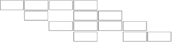
Fig. 9.10
An example of the operation of a 2-stage pipelined router that executes RC and VA in
the first pipeline stage and SA-ST in the next, for the flits of two packets that arrive at two different
input VCs

Search WWH ::

Custom Search