Java Reference
In-Depth Information
G
G
P
H
H
X2
X2
X1
X1
L
L
E1
E2
Y1
Y2
Y1
Y2
(a)
(b)
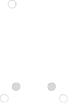
Figure 14.40: (a) Control flow graph; (b) Augmented graph with
preheader
P
and postexits
E
1 and
E
2.
Augmented Flow Graphs
After interval analysis identifies the loop structure of a program, optimizations
may try to reorganize computations inside and outside the loops. To facilitate
further analysis and optimization, the flow graph can be
augmented
with
explicit interval entry and exit nodes. Figure 14.40 demonstrates interval
augmentation as follows:
Preheader
Node
P
is introduced into the graph as the
preheader
for the inter-
val with header
H
. Instead of entering a node at its header, each entry is
redirected to
P
.Thus,theedge(
G
,
H
) is changed to (
G
,
P
) and a new edge
(
P
,
H
) is introduced. The preheader is a convenient place to move code
out of the loop. It can be suitably protected by the loop's continuation
predicate if necessary.
Postexits
The interval shown in Figure 14.40(a) has three exits: from
X
1and
L
to
Y
1, and from
X
2to
Y
2. For each node outside the interval that is
the successor of a node inside the interval, we introduce a
postexit
node.
In Figure 14.40(b), edges into
Y
1 are redirected to
E
1, and similarly with
Y
2and
E
2. Each exit node then has a single edge to its associated node.
Edges are therefore introduced from
E
1to
Y
1andfrom
E
2to
Y
2.
The bold edges in Figure 14.40(b) connect the preheader node
P
with each
postexit node, facilitating reduction of an interval-derived graph.