Geoscience Reference
In-Depth Information
1,0
0,5
A/
(
bh
)
h
′
/h
b/S
0,8
0,4
h
′
/h
h/b
0,6
0,3
h/b
b/S
b
′
/b
0,4
0,2
h/S
b
′
/b
h/S
0,2
0,1
T/
ρ
S
2
T/
ρ
S
2
0
0
0
0,2
0,4
0,6
0,8
1,0
1,2
1,4
1,6
b
1
/S
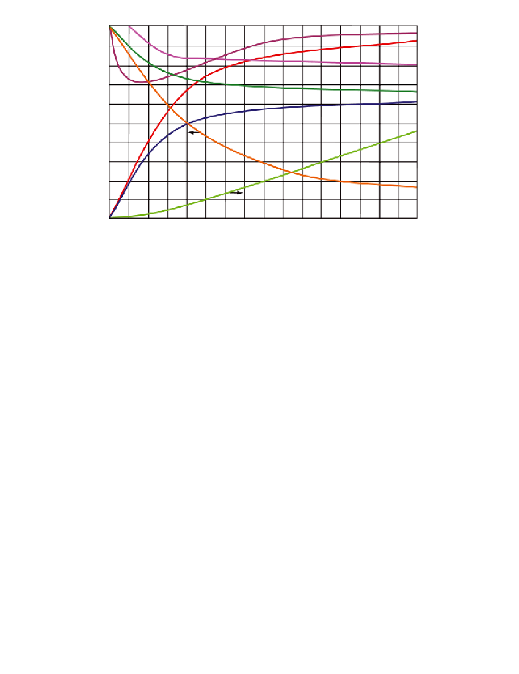
Figure E.6
Plot of the dimensionless ratios. The graph is based on filling with water in air.
bed contact/total width:
b
′
/b
;
height at maximum width/total height:
h
′
/h
;
circumferential tensile load in the geotextile/
ρ
⋅
S
2
:
T/
ρ
⋅
S
2
.
These dimensionless ratios are then combined into a design chart (see Figure E.6)
that can be used for the design of the shape of geotextile tubes filled (under pressure)
with a sand-water mixture. This design chart shows, among other things, that for
b
1
/
S
h
)) of the geotextile tube remains
relatively constant. Given that the tensile load in the geotextile increases significantly
along the same trajectory (by 600%), it is recommended to limit
b
1
/
S
>
0.4 the filled cross-sectional area ratio (
A
/(
b
⋅
≤
0.4, which
results in a relatively flat geotextile tube.