Geoscience Reference
In-Depth Information
T
axial
T
T
T
axial
y
z
T
axial
x
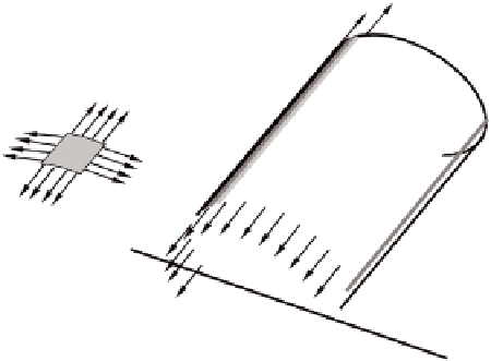
Figure E.4
Axial tensile load in the geotextile.
air
b
S
d
1
h
water
h
′
b
′
Figure E.5
Definition sketch of geotextile tube according to Sylvester.
generates similar results to GeoCoPS. Because Sylvester has shown the solution for dif-
ferent cases in a dimensionless chart, this method is explained in more detail below.
The method is based on small-scale model research with flexible geotextile tubes
(plastic), filled with water, and performed at the University of Western Australia.
Depending on the water pressure in the tube, and its circumference, different values
were determined for both the shape of the geotextile tube (height, width and filled
cross-sectional area) and the tensile load in the geotextile tube. From these results,
relationships were derived between the input parameter ratio (water pressure (
d
1
)/
tube circumference (
S
)) and the following ratios (see also Figure E.5):
height/width:
h/b
;
width/circumference:
b/S
;
filled cross sectional area/rectangle
b
⋅
h
:
A/
(
b
⋅
h
);