Geoscience Reference
In-Depth Information
C
(
x
c
,
y
c
)
T
d
θ
L
= circumference geotextile tube
θ
+
θ
2
P = p
.
ds
r
= curvature
d
θ
S(x
,
y)
−
θ
2
p
0
= pump pressure
T
θ
dS
ρ
= Volumetric mass of the fill material
p
0
y
h
C
(
x
c
,
y
c
)
p
(
x
)
=p
0
+
ρ
x
r
A
2
p
0
+
ρ
h
A
1
S
(
x
,
y
)
x
b
B
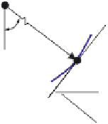
Figure E.3
Definition sketch of geotextile tube for calculations according to Leshchinsky.
is stated as a parameter. This applies when the
geotextile tube is exposed in air. When the geotextile tube lies in water the fill density
parameter
In Figure E.3 the fill density
ρ
is the buoyant fill density.
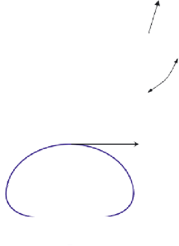
The tensile load in the axial (longitudinal) direction of the geotextile tube is also
determined using the pressure of the fill material (see Figure E.4):
ρ
k
2
∫
)]
yxdx
(E.4)
T
[
(
(
x
p
p
x
=⋅
⋅
l
axia
L
0
0
If the shape of the geotextile tube is known and the pressure is known, this for-
mula can be used to calculate the axial load.
The user can enter the required circumference of the geotextile tube and the pump
pressure and the computer program calculates the corresponding shape of the geotex-
tile tube (height, width and cross sectional area) and the required tensile strength of
the geotextile to be used (based on the calculated tensile load).
SYLVESTER
In Sylvester [25] a design graph for geotextile tubes has been drawn up based on the
results of a small-scale model study. Calculations have demonstrated that this method