Biomedical Engineering Reference
In-Depth Information
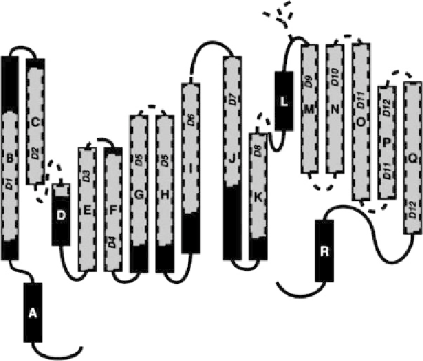
Fig. 1 A schematic representation of CLC channels as deduced from bacterial crystal structure
study [
18
]. A to R refer to new nomenclature of helices, while D1 to D12 refer to the old one. The
old model had the helices as indicated by
shaded areas
and
dashed lines
. Reprinted with
permission from [
9
]. Copyright 2002 the American Physiological Society
had given a very confusing picture. The crystal structure study by Dutzler et al. [
18
]
on two bacterial proteins (
Ec
ClC from
E. coli
and
St
ClC from
S. typhimurium
)
pictured out a dimer with two identical subunits, each of which encloses a pore.
Based on this bacterial study, the membrane topology of CLC channels can
be schematically represented as Fig.
1
[
9
]. Each CLC subunit is composed of 18
a
-helices, most of which do not cross the membrane entirely. Each subunit has an
internal structural repeat, for example, helix B corresponds to helix J; C
corresponds to K, and so on, and the two repeated halves have an antiparallel
orientation, and are directly linked between helices I and J. In the dimeric “double-
barreled” structure of CLC channels as seen in the crystal, the two repeated halves
of each monomer contact each other at helices C and K, and H and P, respectively.
The H-P interaction is supposed to be strong enough for channel assembly, as when
the channel was split between helices J and L, or L and M, respectively,
coexpression of the fragments resulted in functional channels.
The helices H and P (also P and H) exist in the center of the channel and face
each other at the interface between the monomers. Helices H and P link the two
repeated halves within the each monomer and, likewise, helices I and Q (and Q
and I) make intersubunit contacts. Thus, several helices are observed to make
contacts between the two subunits. The cytoplasmic helix A, which is resolved in