Biomedical Engineering Reference
In-Depth Information
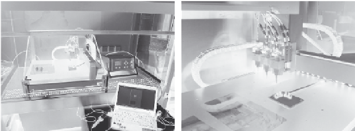
(a)
(b)
FIGURE 4.3
(a) The 3D plotting system including the 3D plotting device, compressed air controller, and
computer to govern the CAD/CAM process. The plotting device is located in a laminar flow
box for operation under sterile conditions. (b) The plotting unit comprises three cartridges
enabling fabrication of scaffolds consisting of three different pasty materials or additional
components like drugs, growth factors, or living cells.
process. After completion of 3D scaffold fabrication, the plotted structure is
transferred into water or other aqueous solutions (e.g., phosphate buffered
saline, cell culture medium) to start the setting reaction. The CPC scaffolds
are hardened within 10 min, but the scaffolds are kept in aqueous media for
a couple of days. During this time, the cement precursors are transformed
to hydroxyapatite, and the oil, which is used for preparation of the storable
P-CPC, is slowly displaced.
3D plotting of CPC scaffolds was carried out in a CAD/CAM process
applying the plotting system shown in Figure 4.3. The Bio-Scaffold-Plotter,
developed at the Fraunhofer IWS Dresden (Germany) on the basis of the
Nano-Plotter
TM
from GeSiM (Groerkmannsdorf, Germany), consists of three
main parts: a plotting device, an air-pressure controller, and a computer
with software required to control the CAD/CAM process (Figure 4.3a).
The plotting device has a platform and a plotting unit with three channels
(Figure 4.3b) that is guided by a high-precision three-axis motion system
allowing movement in the x-, y-, and z-directions. The three channels of the
plotting unit enable simultaneous processing of up to three different pasty
materials or mixtures within one scaffold or implant. Beside the generation
of patient-specific implants by incorporation of biological components, bi- or
triphasic scaffolds for repair and regeneration of defects at tissue interfaces
can be produced (Lode et al., forthcoming).
For plotting, a cartridge equipped with a fine nozzle is filled with P-CPC,
inserted into the plotting unit, and connected with a compressed air supply.
During extrusion of the pasty material forced by compressed air, the nozzle
accomplishes a 3D motion according to the CAD/CAM data set. The plotting
unit moves with a constant speed (plotting speed) along the x- or y-axis or
intermediate x- or y-directions. If plotting of one strand is completed, extru-
sion of the material is stopped and a high tear off speed is applied to disrupt
Search WWH ::

Custom Search