Geology Reference
In-Depth Information
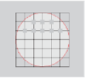
Coil Alone Coil with Drill Collar Layered Media
Figure 8.4.
Detailed transmitter coil models.
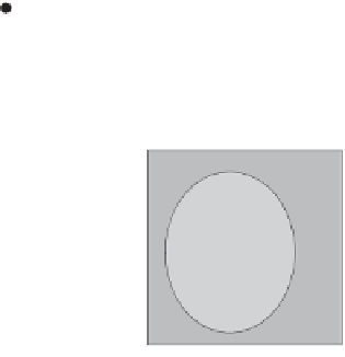
Figure 8.5.
Eccentered coil with invasion.
The objective behind
Electromagnetic Well Logging
is nothing less than a
complete, scientifically rigorous and physically correct description of the actual
borehole logging environment encountered by modern resistivity tools. This
includes accurate modeling of coil transmitters, drill collars, multiple geological
layers, anisotropy and dip angle (interfacial charge creation at bed layer
interfaces, which depends on frequency and conductivity contrast, is modeled by
the coupled scalar potential V in Equations 8.1 and 8.2). The full formulation is
solved using a fast, numerically stable, iterative relaxation solver (in typically
seconds per three-dimensional simulation) and all physical results are
automatically presented in color graphics plots to be given later. In other words,
no approximations are taken, and as such, detailed validations with several
rigorous independent models show excellent agreement. It is important to
emphasize how our model differs from existing ones. Referring to Equations
8.1 and 8.2, classic “induction” models would solve
2
A
-
A
/ t = -
J
s
where V is set to zero and
J
s
is dipolar, which assumes a diffusion process; we
stress that so-called “propagation resistivity” MWD formulations are identical to
this even for frequencies up to the usual 2 MHz. Thus, these processes are also
diffusive and are
not
“propagation” in any sense of the word - any such
reference is a misnomer. On the other hand, methods focused on dielectric
logging, which solve “
2
A
-
A
/ t -
2
A
/ t
2
+ . . . = . . ”
are
wave
propagation in nature provided the dynamics are not critically damped. Our
model solves Equations 8.3.1-8.3.4 in their entirety as shown on the next page
for
both
diffusion and true propagation problems in the frequency domain.


Search WWH ::

Custom Search