Geology Reference
In-Depth Information
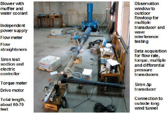
Figure 5.13.
Short “hydraulic” wind tunnel, or simply “short wind tunnel.”
Figures 5.12 and 5.13 describe additional short wind tunnel features. Next,
notice the black tubing leading to the outside of the test shed in Figure 5.13.
Flow through this conduit is normally shut off during signal strength and erosion
testing. When wave interactions over large spatial scales are required, flow is
allowed to pass through this connecting section and into the “long wind tunnel”
shown in Figure 5.14. Mud sirens alone are known to be ineffective in deep
well applications due to low signal strength creation and accompanying high
attenuation at large frequencies. Thus, clever means for pressure amplitude
enhancement are required. These methods were evaluated in the wind tunnel.
For example, multiple “sirens in series” employing synchronized, closely-spaced
sirens rotating in unison provide one form of “constructive wave enhancement.”
This can be augmented by another type of positive wave interaction: we employ
a specially designed form of “frequency shift keying (FSK)” in which changes
in frequency are used to indicate 0's and 1's. Recall that, whenever a created
siren signal propagates upstream, one having opposite pressure polarity is
created that travels downstream. This signal, in the simplest description, reflects
at the drillbit and travels upward to interact with upgoing waves created later.
The frequencies are selected so that proper phasing leads to constructive wave
interference in addition to that using multiple sirens. Good signal strength is
achieved without penalties related to power or erosion. These effects and the
testing of multiple transducer signal processing methods for echo and mudpump
noise removal can be effectively tested in long wind tunnels.


Search WWH ::

Custom Search