Graphics Reference
In-Depth Information
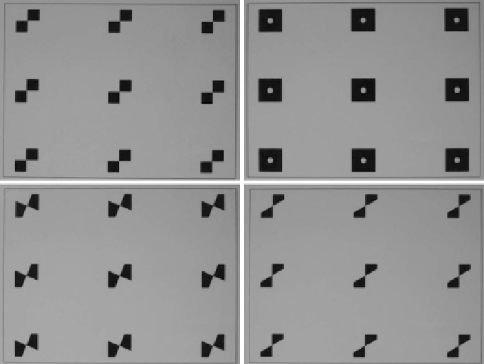
Fig. 1.12
Example input images for the evaluation of the examined chequerboard corner localisa-
tion methods. The
x
axis is in the horizontal and the
y
axis in the vertical image direction
parallel to the normal of its surface. Specifically, our mechanical setup ensures
that the deviations
β
x
and
β
y
from orthogonality of the optical axis with respect
to the
x
and
y
axes of the
xy
-table are smaller than 0
.
5
◦
. If it is assumed that
the optical axis of the camera is inclined horizontally by the angle
β
x
, perspec-
tive foreshortening of the surface of the
xy
-table implies an unforeshortened hor-
izontal pixel scale
s
(
0
)
=
s
x
/
cos
β
x
as long as
β
x
is smaller than a few degrees
(for larger angles the finite distance of the camera from the
xy
-table would be-
come relevant). At the same time, a horizontal displacement
x
in millimetres on
the
xy
-table translates into a horizontal displacement
u
in pixel coordinates of
u
x
xs
(
0
)
xs
x
. Hence, systematic errors of the pixel scale
s
x
and the
horizontal displacement
u
in pixel coordinates due to a small nonzero horizontal
deviation
β
x
from orthogonality compensate each other, and no systematic errors
are introduced.
A nonzero deviation
β
y
of the optical axis from orthogonality in the
y
direc-
tion has the effect that the upper and lower rows of targets (cf. Fig.
1.12
)have
effective horizontal pixel scales which are different from the value
s
x
determined
for the middle row. For
β
y
=
=
cos
β
x
=
x
0
.
5
◦
, the relative differences amount to 0
.
1 % in our
setup but compensate each other on the average—when the pixel scale is higher for
the top row it is lower by the same relative amount for the bottom row, and vice
versa.
Search WWH ::

Custom Search