Graphics Reference
In-Depth Information
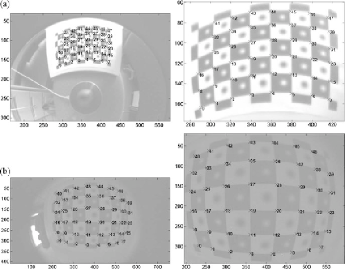
Fig. 1.9
(
a
) Extraction of the calibration rig in an image acquired with a catadioptric omnidirec-
tional camera. (
b
) Extraction of the calibration rig in an image acquired with a fisheye lens. For
both examples, the full image and an enlarged section are shown. The contrast has been reduced
for visualisation
1.4.8.1 Different Types of Calibration Targets and Their Localisation
in Images
Throughout this section it is assumed that the positions of targets are already known
up to a few pixels. This can be achieved by various detectors (Jähne,
2005
; Krüger
et al.,
2004
). Given the positions of the targets in a set of images and their known
world coordinates, a least-mean-squared error between the projected scene points
and the measured image points is minimised. This requires suitable initial parame-
ters such as the per-image transformation or the parameters of the camera model for
each camera to be calibrated. For planar calibration rigs and pinhole cameras these
parameters can be estimated using homographies (Heikkilä and Silvén,
1997
). Salvi
et al. (
2002
) provide a systematic comparison of the accuracies of several camera
calibration techniques relying on nonlinear, linear, and two-step optimisation ap-
proaches for the determination of the intrinsic and extrinsic camera parameters. As
a measure for the quality of calibration they use the average reprojection error in
the image plane and the three-dimensional reconstruction error of selected points
in the scene. For their comparative analysis, a unique set of points extracted from
the images is used for all regarded calibration methods, and no comparison between
Search WWH ::

Custom Search