Graphics Reference
In-Depth Information
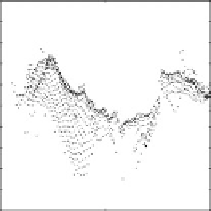
Fig. 6.28
Three-dimensional point clouds generated by the initial blockmatching stereo and by
the specular stereo algorithm (flange example). For clarity, in all diagrams only the part of the
point cloud right of the
dashed line
marked in (
a
)isshown.(
a
) Viewing directions into the point
cloud. A shallow depression in the surface is marked by '
D
'. (
b
) Enlarged part of the three-dimen-
sional point cloud generated by specular stereo as seen from direction 2, showing a side view of the
shallow depression. (
c
) View from direction 1 and (
d
) from direction 2 into the initial three-dimen-
sional point cloud. (
e
) View from direction 1 and (
f
) from direction 2 into the three-dimensional
point cloud generated by the specular stereo algorithm
is reconstructed. These quantities describe how consistent the geometric and the
photopolarimetric data are with each other, given the result of the specular stereo
algorithm.
An intuitive measure for reconstruction accuracy is the appearance of the three-
dimensional point cloud obtained by stereo analysis. In Fig.
6.28
two views into
the three-dimensional point cloud of the ring-shaped flange are shown for the ini-
tial blockmatching stage and for the final result of the specular stereo method. The


Search WWH ::

Custom Search