Graphics Reference
In-Depth Information
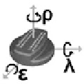
Fig. 6.1
Left
: Definition of the roll, pitch, and yaw angles
ε
,
λ
,and
ρ
.
Centre
and
right
: Reference
pose of the oil cap and typical fault
6.1 Inspection of Rigid Parts
The first typical quality inspection scenario involving the three-dimensional pose es-
timation of rigid parts is detection by pose estimation (cf. Sect.
6.1.1
), corresponding
to a simultaneous detection of the presence and estimation of the pose of an object
of known three-dimensional geometry. In the second scenario, pose refinement (cf.
Sect.
6.1.2
), a reasonably accurate initial pose of the object is required which is then
refined further.
Many applications of pose estimation methods for quality inspection purposes
impose severe constraints on the hardware to be used with respect to robustness and
easy maintenance. Hence, it is often difficult or even impossible to utilise stereo
camera systems, since they have to be recalibrated regularly, especially when the
sensor unit is mounted on an industrial robot. In this section we therefore describe
applications of the monocular pose estimation methods by von Bank et al. (
2003
)
and by Barrois and Wöhler (
2007
) (cf. Sects.
2.1
and
5.6
) in the automobile produc-
tion environment.
6.1.1 Object Detection by Pose Estimation
The inspection task addressed in this section is to detect the presence and to estimate
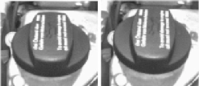
the three-dimensional pose of the oil cap shown in Fig.
6.1
based on the method of
von Bank et al. (
2003
). To generate real-world images with well-defined ground
truth poses, we made use of a calibrated robot system. The accuracy of calibration
with respect to the world coordinate system is about 0
.
1
◦
with respect to camera
orientation and 0
.
1 mm with respect to camera position. As the engine itself is not
part of the robot system, the relation between world coordinate system and engine
coordinate system has to be established separately, which reduces the accuracies
stated above by about an order of magnitude.
First, the difference between the measured and the true pose of the correctly
assembled oil cap is determined depending on the camera viewpoint and the il-
lumination conditions. The scene is illuminated by a cylindric lamp around the


Search WWH ::

Custom Search