Graphics Reference
In-Depth Information
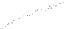
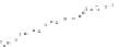
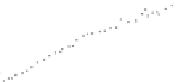
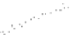
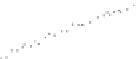
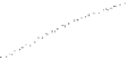
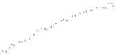
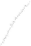
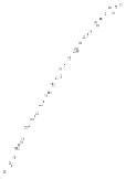
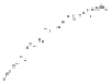
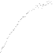
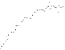
Fig. 4.11
Depth-defocus functions for a lens with
f
=
12 mm and
κ
=
1
.
4(
left
)andalenswith
f
=
20 mm and
κ
=
2
.
4(
right
), fitted to the measured data points according to (
4.15
)
For uniform camera motion, the image index
j
is strongly correlated with the ob-
ject distance
z
. Hence, (
4.15
) is fitted to the measured
(χ, j )
data points for each
corner
i
, such that the location of the maximum of
yields the index
f
i
of the im-
age in which the ROI around corner
i
is best focused. This ROI corresponds to
I
if
i
.
The fitting procedure is applied to introduce robustness with respect to pixel noise.
For non-uniform camera motion, the index
f
i
can be obtained by a parabolic fit to
the values of
χ
around the maximum or by directly selecting the ROI with maxi-
mum
χ
. The depth
z
of each corner is reconstructed from the pose of the complete
rig according to Bouguet (
2007
).
For each tracked corner
i
, the amount of defocus is computed for each ROI
I
ij
,
i.e. the
σ
value relative to the previously determined best-focused ROI
I
if
i
according
to (
4.16
). By employing the bisection method, the value of
σ
is determined for
which the root-mean-square deviation between
G
σ
∗
I
if
i
and
I
ij
becomes minimal.
The depth-defocus function is then obtained by a least-mean-squares fit of (
4.15
)to
all determined
(σ, z)
data points.
Two examples are shown in Fig.
4.11
for lenses with focal lengths of 12 mm
and 20 mm and f-stop numbers of 1
.
4 and 2
.
4, respectively. Objects at a distance of
about 0
.
8 m and 0
.
6 m are in focus, corresponding to the minimum of the curve,
respectively. At the minimum of the depth-defocus function one would expect
a PSF radius of zero, but the influence of pixel noise may yield small nonzero
positive values of
σ
ij
near the minimum, leading to the behaviour observed in
Fig.
4.11
.
S
4.2.3.3 Determination of the Depth Map
Stationary Camera
An example result by Barrois and Wöhler (
2007
)ofthe
depth from defocus method based on a pixel-synchronous pair of images acquired
at different f-stop numbers with a stationary camera is shown in Fig.
4.12
for a door
hinge. This procedure may be automated using a lens equipped with a motorised


Search WWH ::

Custom Search