Graphics Reference
In-Depth Information
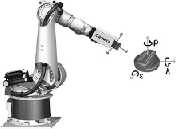
Fig. 2.1
Sketch of the
robot-based inspection
system with a definition of
the pose angles
ε
(roll),
λ
(pitch), and
ρ
(yaw) in the
camera coordinate system
procedure by representing a group of similar templates by a single prototype tem-
plate and a distance parameter. A recursive application of this grouping scheme
eventually results in a hierarchy of templates, which is generated in a bottom-up
manner using simulated annealing-based partitional clustering. Each node of the hi-
erarchical tree of templates requires matching of a prototype template
p
with a part
of the image. To avoid an exhaustive search, locations of interest for the nodes in
the hierarchy one level below a certain prototype template ('children nodes') are
determined by selecting the positions for which the distance measure between the
respective prototype and the image falls below a predefined threshold
θ
p
.Thispro-
cedure is repeated for the children nodes until the tree has been traversed. If, on
the other hand, the distance measure exceeds
θ
p
, the search is not continued in the
next level of the tree. The high computational efficiency of this method results from
the fact that, according to the hierarchical approach, only a small fraction of the
templates actually need to be matched with parts of the image.
In our system, we do not need to estimate scale—the distance to the object is as-
sumed to be known at an accuracy of better than 3 % due to the fact that the system
is designed for an industrial quality inspection scenario in which the approximate
position of the parts is provided by CAD data. Template matching does not have
to search all scales explicitly. Hence, the original pose estimation problem of de-
termining six degrees of freedom can be reduced to a five-degree-of-freedom (three
pose angles and two image position coordinates) problem.
For pose fine-tuning, the pose angles are interpolated between the
n
b
'best' tem-
plate matching solutions, with
n
b
=
30 in our system. This is justified, because in
our pose estimation scenario the dissimilarity values of the 30 best solutions usu-
ally do not differ by more than about 20 %, and thus all these solutions contain a
significant amount of information about the pose.
In many applications, templates are generated from real-world image data (De-
mant,
1999
). For inspection tasks, however, one can assume that a CAD model of the
object to be inspected is available. We therefore generate realistic two-dimensional
templates from CAD data using the public domain software POVRAY, simulating
the properties of the surface material and the illumination conditions by employing
ray tracing techniques. The pose of the object is defined by the three angles
ε
(roll),
λ
(pitch), and
ρ
(yaw), as shown in Fig.
2.1
. Typical matching results are shown
Search WWH ::

Custom Search