Biomedical Engineering Reference
In-Depth Information
Bottom
Bottom side view
Top
Cross-sectional view
1 µm
FIGURE 5.7
Morphologies of TiO
2
nanotube arrays acquired by anodization of Ti. Upper images are architecture from anod-
ization in ethylene glycol electrolyte; lower image is architecture from Ti anodization in an aqueous KF bath.
(From Grimes, C.A., Mor, C.K.,
TiO
2
Nanotube Arrays. Synthesis, Properties, and Applications
, Springer Science,
New York, NY, 2009. With permission.)
by a barrier layer of metal oxide. Both well-separated, stand-alone nanotubes and densely
packed arrays can be acquired by using different electrolytes.
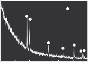
Generally, the as-prepared titania nanotubes are amorphous as suggested by both x-ray
diffraction (XRD) and selection area diffraction (SAD) patterns. As shown in Figure 5.8,
only peaks from crystalline titanium are present in the spectrum acquired after anodiza-
tion in the NaF +Na
2
SO
4
electrolyte. Nguyen has systematically studied the detailed struc-
ture of titania nanotubes using TEM and high-resolution TEM (HR-TEM). The nanotube is
fabricated in an ethylene glycol solution containing 0.5 wt.% NH
4
F at a constant potential
of 20 V for 1 h (Nguyen et al. 2009). As shown in cross-sectional TEM pictures in Figure
5.9, the tubes are always oriented perpendicular to the metal surface. Adjacent tubes are
connected by ridges that run perpendicular to the tube length. In addition, a barrier layer
Ti
20
30
40
50
60
70
80
2
θ
(deg)
FIGURE 5.8
XRD pattern of titania nanotube arrays acquired by anodization in electrolyte containing 0.1 m/L NaF and
1 M/L Na
2
SO
4
at 20 V for 2 h.


Search WWH ::

Custom Search