Biomedical Engineering Reference
In-Depth Information
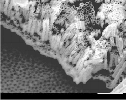
FIGURE 5.4
Cross-sectional views of a 720-μm-thick membrane synthesized using a fixed 60 V potential for double-sided
anodization of Ti plate. (From Prakasam et al.,
J. Phys. Chem.
C
, 111, 7235-7241, 2007. With permission.)
glycol (EG), di-ethylene glycol, formamide (FA),
N
-methyformamide (NMF), and diethyl
sulfoxide (DMSO) in combination with HF, KF, NaF, NH
4
F, or BnMe
3
NF to provide fluo-
ride ions to produce nanotube arrays with lengths up to 1000 μm (Michailowski et al. 2001;
Jung et al. 2002, Kobayashi et al. 2002; Cai et al. 2005). A typical morphology of this type
of titania nanotube arrays is presented in Figure 5.4. The fourth-generation fabrication
technique utilizes nonfluoride-based anodization electrolytes (Grimes and Mor 2009) and
a representative example is shown in Figure 5.5. Some important electrolytes used in the
fabrication of the four generations of nanotube arrays are summarized in Table 5.1.
Mechanism of Nanotube Array Formation
The key processes in the growth of nanotube arrays are:
1. Growth of oxide at the metal surface due to reactions between the metal and O or
OH
−
ions
2. Migration of the metal ions through the metal to the metal/oxide interface
3. Field-assisted dissolution of oxide at the oxide/electrolyte interface
4. Chemical dissolution of the metal/oxide in the acidic electrolyte
0.869
µm
-0.098
µm
5.0 kV
×
20,000 WD 4.1 mm
1
µm
SEI
FIGURE 5.5
Representation of SEM morphology of fourth generations of nanotube arrays fabricated in HCl electrolytes.
(From Allam et al.,
J. Mater. Chem.
, 18, 2341-2348, 2008b. With permission.)


Search WWH ::

Custom Search