Information Technology Reference
In-Depth Information
All patterns computed in the xz-plane show a nearly isotropic behavior within the
range from -45° to 45°, as in the case of a typical
cos(
)
source. Furthermore, a
maximum difference of just 2.5 dB can be appreciated between the pattern computed
at the design frequency of 11.5 GHz and that computed at the extremes of the
considered frequency range. The overall behavior of the unit cell assures good
performances within the frequency span ranging from 11.25 GHz up to 12.6 GHz,
thus the proposed configuration can be fruitful adopted to design reflectarrays having
reconfiguration capabilities in a quite large frequency range.
ʸ
3
Preliminary Experimental Results
A preliminary test on the validity of the proposed configuration is performed in the
Microwave Laboratory of the University of Calabria on a 10 GHz prototype
characterized by the following features (Fig. 1): L=8.9mm, W=6.8mm, L
a
=6.7mm,
W
a
=0.7mm, r
1
=4.3mm, r
2
=2.7mm,
ʵ
r2
=6.15,
h=0.762mm. A far-field measurement setup (Fig. 7(a)) is adopted to detect the phase
of the field reflected by a small array of 5×5 elements loaded by identically biased
varactor diodes (Microsemi MV31011-89).
ʵ
r1
=2.33, t=0.762mm, d=1.524mm,
(a)
(b)
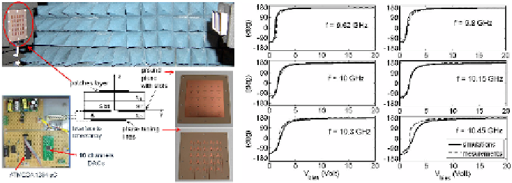
Fig. 7.
Experimental test: (a) Measurement setup; (b) Comparison between simulated and
measured phase curves at different frequencies
The bias voltages are controlled through the circuit board in Fig. 7(a), composed by
a microcontroller (ATMEGA 1284) and a chip with 16 channels integrated DACs
(AD5360). By changing the applied bias voltage from 0 V to 20 V, a continuous phase
shift up to 320° is obtained within the frequency range [9.6
10.45] GHz, (Fig. 7(b)).
An improved operational bandwidth is observed with respect to the value obtained in
the case of the same reflectarray cell driven by a linear phase tuning line. The
simulation of this last case, in fact, gives a smaller reconfigurability frequency range
limited between 9.9 GHz and 10.2 GHz.
÷
Search WWH ::

Custom Search