Environmental Engineering Reference
In-Depth Information
1.0
0.5
0.0
−0.5
5.0
−
1.0
2.5
−
5.0
0.0
y
−
2.5
−2.5
0.0
x
2.5
−5.0
5.0
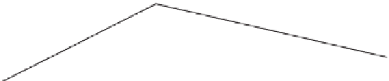
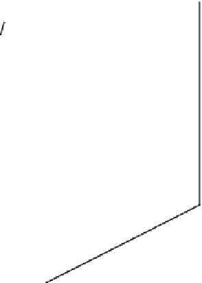
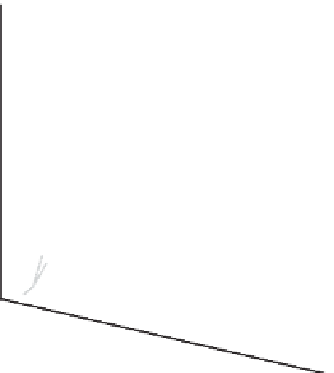
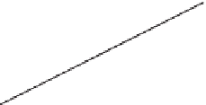
Figure 12.1 The plane wave
f(
x
,t)
at two different times. The lighter shaded wave is at
the earlier time and the wave travels in the (1,1) direction.
from the viewpoint of an observer in
S
let us first be clear on what kind of wave
Eq. (12.16) describes. Figure 12.1 shows a plot of
f(
x
,t)
at two different times
for a particular choice of wavevector
. So that we could draw the picture in the
page we picked a two-dimensional wave. The figure illustrates that Eq. (12.16)
describes a wave travelling in the direction indicated by
k
k
(to produce the figure
we picked
(
1
,
1
)
). In addition, the displacement of the wave is constant along
lines in the
xy
-plane which lie perpendicular to the direction of propagation
k
=
.In
three-dimensions the situation is much the same except that the displacement of
the wave is now constant on planes that lie perpendicular to the wavevector
k
.
For this reason such waves are often referred to as 'plane waves'. The speed of
propagation in
S
is given by
v
k
).
Now we return to the task in hand. What does this wave look like from the
viewpoint of an observer in
S
? This question is explored in detail in one of the
problems at the end of this chapter but for now we need only the result that the
phase of the wave must be a four-scalar, i.e.
=
ω/k
(where
k
= |
k
|
φ
=
k
·
x
−
ωt
(12.17)
must be the same in all inertial frames. This follows since a particular value of
φ
corresponds to a particular state of the wave and this cannot depend upon inertial
frame. For example, the phase difference between a maximum of displacement and