Environmental Engineering Reference
In-Depth Information
x
2
L
12
x
1
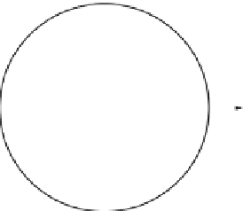
Figure 10.10 Rotation of a solid cube about an edge results in a rotating angular momentum
vector in the lab frame. The component of
L
in the
x
1
−
x
2
plane,
L
12
, describes a circle
about the
x
3
axis.
and the vector equation Eq. (4.9) reduces to
d
L
d
t
I
3
d
ω
d
t
=
=
τ.
(10.43)
There is a subtlety here that is well worthy of a mention. Eq. (4.9) is derived only
in the case that the centre-of-mass does not accelerate but we may be interested in
cases other than that. However, in this special case
e
3
is a fixed direction in space
and so Eq. (10.43) is still valid. If
e
3
were not fixed in an inertial frame then we
would need to remember to include the term
I
3
ω
d
e
3
/
d
t
when we compute d
L
/
d
t
.
Notice also that for fixed
ω
, it is possible to have rotations about a principal
axis without the need for a torque. This is a special feature of rotations about a
principal axis.
The other type of fixed-axis rotation occurs when a body rotates about an axis
other than a principal axis. In this case, a torque is needed in order to sustain
the rotation and this might ordinarily be provided by a fixed axle. We already
investigated an example of rotation about an axis other than a principal axis when
we considered a cube rotating about one side, in Example 10.2.2. In the following
example we will return to that scenario and determine now the torque required to
sustain the rotation.
Example 10.4.1
A solid uniform cube rotates at constant angular speed ω about a
fixed axle attached to one edge of the cube. Calculate the magnitude of the torque
provided by the fixed axle.
Solution 10.4.1
To calculate the torque we need to work out the rate of change of
L
. In Example 10.2.2 we showed that
1
4
−
Mb
2
ω
1
4
L
=
−
.
(10.44)
2
3