Environmental Engineering Reference
In-Depth Information
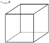
Note that the angular momentum and the rotational velocity are not parallel in this
case (see Figure 10.7). Also note that the direction of
L
is fixed in the body-fixed
frame in which we computed
I
but that in the lab frame it rotates with the cube, i.e.
about the x
3
axis with angular frequency ω.
w
x
3
x
2
L
x
1
O
Figure 10.7
A cube rotating about an axis along one edge.
10.3 PRINCIPAL AXES
We have looked at some situations where an obvious symmetry helps us to
simplify the moment of inertia tensor. In the general case it is still possible to
simplify things through a good choice of the coordinate axes. Although we do
not prove it here, it is a theorem of linear algebra that as long as the inverse of
I
, written
I
−
1
,exists(i.e.
II
−
1
is the identity) then there must also exist a set of
orthogonal basis vectors in which
I
takes on the diagonal form
I
1
00
0
I
2
0
00
I
3
.
I
=
(10.28)
The axes defined by this choice of basis are known as principal axes. Since there
is no ambiguity, we use only one index for the principal axis elements of
I
,
i.e.
I
1
≡
I
11
etc. The diagonal elements
I
1
,I
2
and
I
3
are known as the principal
moments of inertia.
For the special case of rotation about a principal axis, e.g. the
x
1
axis, we have
I
1
00
0
I
2
0
00
I
3
ω
0
0
I
1
ω
0
0
=
=
(10.29)
L
or
L
=
I
1
ω
, which means that
L
and
ω
are parallel. In general, when
ω
has com-
ponents along more than one principal axis,
L
will not be parallel to
.
The task of determining the principal axes and the principal moments of inertia is
an exercise in linear algebra. If ˆ
ω
α
represents a principal axis, and
I
α
is the principal