Biomedical Engineering Reference
In-Depth Information
1.0
0.8
0.6
max
0.4
D
i
, m
V
, L
0.085 2
0.075 2
0.051 0.25
0.041 0.25
0.032 0.25
0.2
0.0
0
10
20
30
2
D
i
D
R
-
D
i
, s
-1
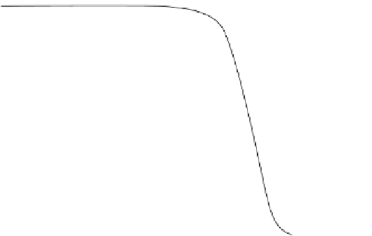
FIGURE 18.2
Relative growth rate of FS-4 animal cells on microcarriers as a function of the integrated shear factor
(data from Croughan MS, Sayre ES, and Wang DIC. “Viscous reduction of turbulent damage in animal cell culture”,
Biotechnol. Bioeng. 33:862, 1989). D
R
is the reactor vessel diameter, D
i
is the impeller diameter, V is the volume of the
reactor, and
u
is the rotation rate of the impellers.
Fig. 18.3
b shows a schematic of marine style impellers. Marine impellers throw fluid upward
and thus causing top and bottom mixing to occur more easily.
Table 18.2
shows some criteria for the impeller selection. Disc and turbine impellers pump
fluids in radial flow in the vessel. The impellers are generally 30
e
40% of reactor diameter.
(a)
(b)
FIGURE 18.3
Disc and turbine impeller (a) and marine style impeller (b).


Search WWH ::

Custom Search