Biomedical Engineering Reference
In-Depth Information
-r
A
=
kC
A
(C
A0
-
C
A
)
1
-r
A
PFR
CSTR
0
C
Ae
C
A1
C
A0
0
C
A
FIGURE E5-5.2
A sketch of the equal-volume CSTR and PFR reactor in series system for an autocatalytic
reaction.
r
A
)
1
vs
C
A
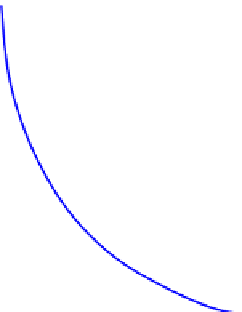
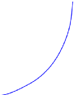
plot. This figure
helps us understand the volume of the CSTR is proportional to the rectangular area with the
top line corresponding to the reactor exit condition. Lower (
Figure E5-5.2
illustrates the solution of this example on the (
r
Ae
)
1
or higher reaction rate at
the reactor outlet reduces the reactor volume requirement. The volume of the PFR, on the
other hand, is proportional to the area under the rate curve.
5.6. RECYCLE REACTORS
Recycle reactors represent cases where part of the reactor effluent is returned to the reactor
inlet. In particular, this setup is useful for recycling the unreacted reactants, and/or catalysts.
To simplify the derivations, we introduced a new (fictitious) flow rate: flow rate of total
unreacted A (TUA). TUAmeans that all the products are reacted (reversely) back to reactant A.
Figure 5.15
shows illustrations of how CSTR and PFR can be setup in general. The feed is
consisted of A (
F
A0
) and some products (
F
TUA0
may not be equivalent to
F
A0
). The required
effluent from the reactor system consisted of
F
Ae
and overall conversion
f
Ae
. If we use conver-
sion to work through the problem, we have the fractional conversion at the inlet to the reactor
system:
F
TUA
0
F
A
0
F
TUA
0
f
A
0
¼
(5.69)
The fractional conversion of A leaving the reactor system is given by
F
TUAe
F
Ae
F
TUAe
f
Ae
¼
(5.70)
Let us assume that the ratio of flow that is recycled is
R
(recycle ratio) times the flow rate
leaving the reactor system. Since there are no other outlets leaving the reactor system, the
total molar flow rate at the only inlet (to the reactor system) and the outlet are identical.


Search WWH ::

Custom Search