Geography Reference
In-Depth Information
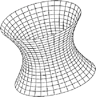
Figure
23.9
is a computer graphic illustration of the
cooling tower
by means of an
oblique
orthogonal projection
which is generated in the following way: A rotation around the 1-axis,
2-axis and 3-axis parameterized by means of
Cardan angles
{
α
∈
[0
,
2
π
]
,β
∈
[0
,π
]
,γ
∈
[0
,
2
π
]
}
transforms (
X
,
Y
,
Z
)into(X
,Y
,Z
), namely
⎡
⎤
⎡
⎤
X
Y
Z
X
Y
Z
⎣
⎦
=
R
3
(
−γ
)
R
2
(
−β
)
R
1
(
−α
)
⎣
⎦
⎡
⎤
cosh
V
cos
U
cosh
V
sin
U
sinh
V
⎣
⎦
=
R
3
(
−γ
)
R
2
(
−β
)
R
1
(
−α
)
(23.13)
The oblique orthogonal projection, in consequence, is defined by Box
23.8
where (
x, y
) are the
Cartesian
coordinates of the
oblique plane
which cover
2
.
R
2
).
Box 23.8 (Oblique orthogonal projection of hyperboloid
H
x
=
Y
y
=
Z
(23.14)
M
2
:=
H
2
,
=20
◦
Fig. 23.9.
Oblique orthogonal projection of the rotational symmetric hyperboloid
α
=
β
=
γ
Next we aim at a
conformal mapping,
an equiareal mapping and an
equidistant mapping
of the
hyperboloid with boundary
onto a circular cylinder
2
parallel to the 3-axis (normal placement)
C
2
. The mapping equations are generated in such a way that
within the cylindric mapping the hyperbolic latitude
V
= 0 produces
y
= 0. Consult Fig.
23.10
for an illustration of the projection geometry.
At first we set-up the mapping equations for the case circular cylinder
which is in vertical contact with
H
2
C
1
,namely
x
y
=
U
(23.15)
f
(
V
)


Search WWH ::

Custom Search