Hardware Reference
In-Depth Information
If the regulator is rated at a maximum of 1.5 A at 7 V (input), the power maximum
for the regulator is about 10.5 W. If we apply an input voltage of 8.4 V instead of 7, we can
derive what our 5 V maximum current will be:
P
V
I
=
max
max
in
10 5
84
125
.
W
V
=
.
=
.
A
From this, we find that the 8.4 V battery regulator circuit can provide a maximum of
1.25 A at the output, without exceeding the regulator's power rating. Multiply 8.4 V by 1.25
A to convince yourself that this equals 10.5 W.
DC-DC Buck Converter
If the application is designed for data acquisition, for example, it is desirable to have it run
as long as possible on a given set of batteries or charge cycle. A switching regulator may
be more suitable than the linear regulator.
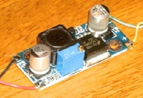
Figure
2-7
shows a very small PCB that is about 1.5 SD cards in length. This unit
was purchased from eBay for $1.40, with free shipping. At these prices, why would you
build one?
Figure 2-7.
DC-DC buck converter
They are also simple to use. You have + and - input connections and + and - output
connections. Feed power in at one voltage and get power out at another voltage. This is so
simple that you'll forgive me if I omit the diagram for it.
But don't immediately wire it up to your Raspberry Pi
, until you have calibrated the
output voltage. While it
might
come precalibrated for 5 V, it is best not to count on it. If the
unit produces a higher voltage, you might fry the Pi.