Hardware Reference
In-Depth Information
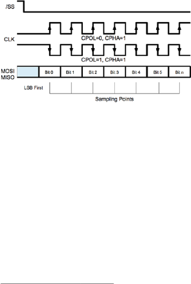
Figure 13-3.
SPI signaling modes 1 and 3
While the four different modes can be confusing, it is important to realize that the
data is sampled at the same times within the data bit cells. The data bit is always sampled
at the midpoint of the data cell. When the clock phase is 0 (CPHA = 0), the data is sampled
on the trailing edge of the clock, whether falling or rising according to CPOL. When the
clock phase is 1 (CPHA = 1), the data is sampled on the leading edge of the clock, whether
rising or falling according to CPOL.
Slave Selection
While some protocols address their slaves by using transmitted data, the SPI bus simply
uses a dedicated line for each slave. The Raspberry Pi dedicates the GPIO pins listed in
Table
13-2
as slave select lines (also known as chip enable lines).
Table 13-2.
Raspberry Pi Built-in Chip Enable Pins
GPIO
Chip Enable
P1
8
CE
0
P1-24
7
CE
1
P1-26
The Raspbian Linux kernel driver supports the use of only these two chip enable
lines. However, the driver is designed such that you don't have to use them, or only these.
It is possible, for example, to add a third GPIO pin as a slave select. The application
simply takes responsibility for activating the slave select GPIO line prior to the data I/O
and deactivates it after. When the driver is controlling the two slave selects, this is done
automatically.