Hardware Reference
In-Depth Information
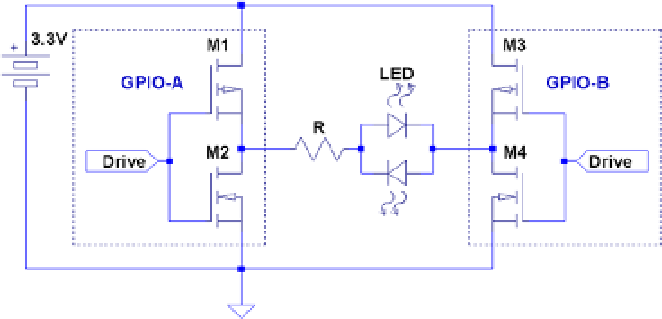
Figure 10-7.
Driving a bi-colored LED
The pair of GPIO outputs form an H-Bridge because each of the outputs themselves
are a pair of CMOS driving transistors—an upper and lower half. It is this pairing that
makes them capable of both sourcing and sinking a current. By using two GPIO outputs,
you form an H-Bridge driver.
To light the bi-color LED in one color, make one GPIO high (source), while the other
is made low (sink). Then the current will flow through the LED from the first GPIO output
into the second. To reverse the current and see the other color, make the first GPIO low
and the other high. Now the current flows from the second GPIO output into the first.
Testing Drive Strength
There's nothing like finding out for yourself the configured parameters of your Raspberry
Pi. The program
pads.c
(next) dumps out the GPIO Pads Control registers so that you can
verify the actual parameters in effect.
Each GPIO pin defaults to setting 3 (for 8 mA).
28
Running the
pads.c
program on my
Rev 2.0 Raspberry Pi showed that the GPIO group from 28 to 45 was configured for
16 mA
.
GPIO pins 28 to 31 are available on header P5.
The following example session shows the output for my Raspberry Pi:
$ sudo ./pads
07E1002C : 0000001B 1 1 3
07E10030 : 0000001F 1 1 7
07E10034 : 0000001B 1 1 3
The last four fields on each output line are as follows:
1.
The word value in hexadecimal
2.
The configured slew rate setting
3.
The configured hysteresis setting
4.
The drive-level code