Biomedical Engineering Reference
In-Depth Information
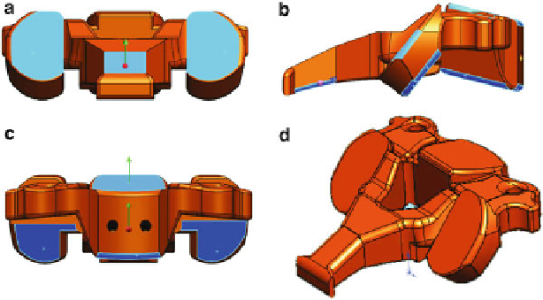
Fig. 7.12
3D views of the constructed C2 vertebra: (
a
) frontal view, (
b
) lateral view, (
c
) posterior
view, (
d
) isometric view
•
Highly maneuverable
•
Small fi le size
•
Can be adapted and modified at any time
Due to its advantages, the model can be further more developed by attaching an
anterior stabilization plate on it.
The geometrical modeling of the functional implanted unit involves two different
aspects of modeling: the design of the anatomical elements and design of the
mechanical elements. Using
Feature Based Design
module of the SolidWorks envi-
ronment, the anatomical and mechanical elements were modeled [
3,
10,
35,
50
] .
The model of the functional unit of the cervical spine is composed of the follow-
ing basic elements: two vertebrae (C2 and C3 in our case), intervertebral disc, inter-
spinous ligament, two facet joints, spinal cord, and vertebral arteries. Certainly, the
natural functional unit is far more complex than that, but the proposed functional
unit successfully fulfills the shape and functioning requirements with the mentioned
elements.
To accomplish the functional requirements of the cervical unit, a great attention
was paid in building the shape details of each element, and the contact surfaces
between the various elements.
The modeling complexity is proved by the number of operations on the vertebra,
as many as 70 for each vertebra. In design process, operations like extruded boss,
extruded cut, revolved cut, swept boss, fillet, chamfer, simple hole, and loft were
used, starting from various primitive sketches. The modeling concept was based on
extrude cutting
of different contours, from a 3D block.
The result of the primitive sketch subtractions, together with many
feature
opera-
tions, leads to a C2 vertebral body having the shape and functional surfaces simi-
larly to the natural one. In Fig.
7.12
, different views of vertebral body are presented.
Search WWH ::

Custom Search