Biomedical Engineering Reference
In-Depth Information
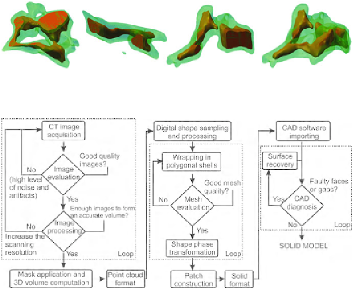
Fig. 7.9
3D views of the multi-solid vertebral body in transversal section, frontal section, sagital
section, and isometric view
Fig. 7.10
Image to solid transformation protocol
The protocol indicates a successful way to generate a complex shape solid body.
The protocol can be applied to any scanned images in order to obtain solids.
The cervical vertebra presented in Fig.
7.9
can be used to model the functional
unit of the cervical spine. Additionally, soft tissues like facet joints, ligaments, mus-
cles, spinal cord, and nerves can be integrated into the structure in order to achieve
a more realistic model.
The soft tissues of the cervical unit have not been part of the reconstruction pro-
cess. Elements like the intervertebral disc, facet joints, interspinous ligament, spinal
cord, and nerves were modeled using classical CAD tools. The reconstruction of
these tissues can be possible by MRI scanning of a living cervical spine, the CT
scanning being not adequate for soft tissue reconstruction.
The reconstructed elements together with the modeled ones were assembled in
one compact structure which is presented in Fig.
7.11
, in posterior and anterior
views. The muscle development was not yet modeled, representing a further work.
The relations between elements are coincidence, tangency, concentricity, paral-
lelism, and distances.
CAD environment offers data about the properties of the multi-solid bodies such
as mass, volume, moments of inertia, and mass center. The existence of these prop-
erties proves the availability of the model for mechanical simulation tests.
Search WWH ::

Custom Search