Biomedical Engineering Reference
In-Depth Information
Analysis of retrieved bioresorbable interference screw confirmed that future
research should be directed to the improvement of material properties using new
composite materials (e.g., hydroxyapatite components which facilitate the bone
in-growth). Attention should be given to the screw self-tapping design which will
assure reduction of breaking forces and avoid damaging the soft tissues, espe-
cially the of the reconstruction graft.
6.3.2
Innovative Design of a Bioresorbable Interference Screw
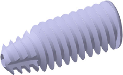
Based on clinical experience and finite element simulations, a new bioresorbable
interference screw design is proposed. The self-tapping interference screw has the
following main design particularities (Fig.
6.11
):
•
The shape of the screw is cylindrical at the proximal end and tapered at the distal
end for approximately one-third of the whole screw length.
The thread depth of 1.5 mm (for a screw of 10 mm diameter) for the proximal
•
cylindrical zone, progressively decreasing along the conical zone.
The shape of the thread differs for the cylindrical and tapered zones; the passage
•
from a shape of the thread to the other is made progressively, no sharp edges
being generated; double-helix thread with constant pitch of 2 mm.
Hexagonal interior channels with different dimensions for the cylindrical and
•
conical zones.
Three cutting flutes uniformly distributed on the conical part of the screw.
•
•
Proximal rounded thread edges.
Different designs of the interference screw were obtained by varying the attack
angles (the first angle of the thread flank in the insertion direction) for the distal and
proximal zones (25°/30°, 25°/40°, 30°/30°, 30°/40°). In order to assess the influence
of these angles on the screw holding strength, several FE simulations were per-
formed using ANSYS v12 software (Figs.
6.12
,
6.13
,
6.14
,
6.15
,
6.16
, and
6.17
).
The maximum displacement for each screw design and the equivalent von Misses
stresses were calculated in a static structural analysis in which the tendon was loaded
along the tunnel axis at 200N, according to the data presented in literature [
74
] .
Fig. 6.11
3D CAD model of the
innovative interference screw
Search WWH ::

Custom Search