Biomedical Engineering Reference
In-Depth Information
(A)
(B)
(C)
90
µ
m
90
µ
m
90
µ
m
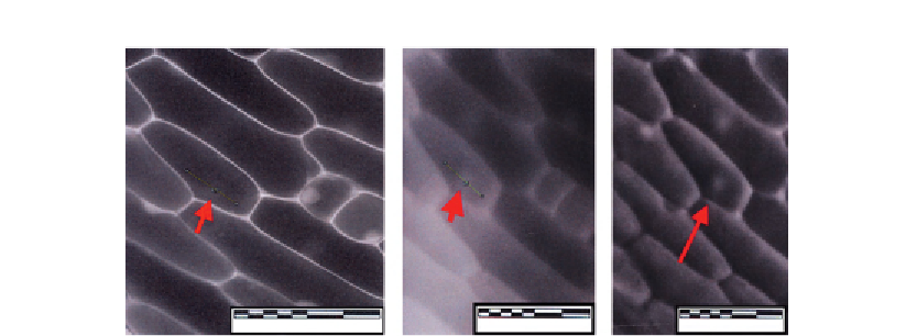
Figure 4.3
Onion inner epidermis from bulb scale in brightfield (A), low pass filter (B),
and high pass filter (C).
Mitigation of the halos surrounding the phase delays are currently utilized by Nikon as
apodized phase microscopy and reduce the halos considerably.
Let us consider a specimen to be imaged by annular illumination with a phase ring in the
objective which matches it.
Figure 4.2
is of an onion inner epidermis nucleus showing contrast variations in black and
white caused by phase differences due to different materials and different concentrations.
The alternative method of phase contrast imaging uses the transport of energy formulation.
Results are published by Barone-Nugent et al.
[11]
for fossils with relatively opaque
specimens, cells with absorbing structures such as algae like Spirogyra and for phase view
which has a similar development of algorithms was also done in a French company
(
Figure 4.3
).
4.4 Becke Line in Optical Microscopy
The method developed by Becke gives an easy determination of the refractive index of the
desired object
[12]
. This is often used in mineral microscopy for looking at objects with a
refractive index which one wishes to estimate and is applicable to botanical specimens. It is
one of the earliest contrasting methods made between specimens and their surroundings and
is due to their phase differences.
Figure 4.4A
explains how the Becke lines appear between transparent materials of different
refractive indices. This figure demonstrates the case where a specimen that is denser than
its surroundings (i.e., higher refractive index) is placed on the stage of the microscope.
When elevating the objective or lowering the stage of the microscope, the Becke line will
Search WWH ::

Custom Search