Biomedical Engineering Reference
In-Depth Information
excitation optics and a TD or SD detection module. In this section, we will describe
in detail the experimental implementations of FPM in both TD and SDs.
18.3.1 Time-Domain Fluorescence Phase Microscopy
A TD-FPM system is shown in
Figure 18.2
. The detector output in the case of a single
fluorescent emitter is related to:
I
ð
x
;
y
;
z
Þ 5
I
0
ð
x
;
y
Þf
1
1 jγð
2z
Þj
cos
ð
2k
0
z
Þg
(18.1)
Here, k
0
is the central emission wavenumber of the source, I
0
(x,y) is the transversal image
of the source,
(
) is the absolute value of the normalized source autocorrelation function,
and z is the position of the source (relative to the zero differential optical path-length point
z
0
of the self-referencing interferometer). The axial (depth) position of the source (z) can be
retrieved by axially scanning the source through the depth of field (which is kept greater
than the coherence length of the source or the z dimension of the object under observation)
followed by the identification of the central fringe position. As a result, the axial (depth)
localization precision is determined by the coherence length of the source (which is on the
order of a few micrometers), where only fluorescent markers for which the coherence
condition is satisfied produce self-interference patterns. Alternatively, TD-FPM can employ
phase-shifting methods to extract the amplitude of self-interference patterns at various z
positions of the fluorescent source and reconstruct the source autocorrelation function.
The profile formed by these amplitudes determines the mesoscopic axial PSF—and hence
the optical depth sectioning capabilities—of the FPM system. In addition, TD-FPM can
make use of phase-shifting techniques to retrieve the phase maps of I(x,y,z)in
Eq. (18.1)
γ
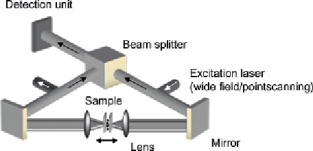
Figure 18.2
Experimental setup of TD-FPM. Fluorescence waves emitted from a fluorescent sample positioned
in a self-referencing interferometer comprising two matched opposing lenses are directed by
mirrors to a beam splitter where they recombine. The sample can be excited by either a wide-field
or a point-scanning illumination and is scanned to generate the interference pattern on the
detection unit (e.g., a camera). Source: This figure is reproduced from figure 3(a) of Ref.
[40]
with
permission of John Wiley & Sons Ltd.

Search WWH ::

Custom Search