Biomedical Engineering Reference
In-Depth Information
To achieve phase images with optimum spatial resolution, two conditions need to be met.
First, the period of spatial fringes should be no larger than the diffraction-limited spot, which
corresponds to approximately 0.3
m at the sample. Second, for the adequate sampling of the
fringe, the pixel resolution should be fine enough to have at least 3 pixels per fringe. Typically,
it is optimal to set 4 pixels per fringe. For our camera pixel size of 17
μ
m, the magnification is
set to be 250 such that the 4 pixels correspond to 272 nm, thus satisfying both conditions.
μ
In the original TPM experiment
[13]
, due to the rotation of the sample beam, the fringe
spatial frequency varied in magnitude from 0 to its maximum value
k
jθ
j
/
M
, where
max
k
5
2
. This large variation in spatial frequency impedes the maintenance of an optimal
spatial frequency of the interference fringe. To avoid this problem, a fixed tilt of the
reference beam is introduced in a direction normal to the sample beam tilt, with an angle
such that in the absence of sample beam tilt, there are 4 pixels per fringe in the
y
-direction,
as illustrated in
Figure 12.11
. The fringe period is fixed along the
y
-direction as the sample
angle is varied from
2
θ
max
to
1
θ
max
(
Figure 12.11B
D
). To calculate quantitative phase
images we applied the demodulation process only along
y
-direction.
π
/
λ
(A)
k
R
Image plane
k
S
(-
θ
max
)
k
S
(0)
k
S
(
θ
max
)
θ
= -
θ
max
θ
= 0
θ
=
θ
max
(B)
(C)
(D)
3
(E)
(F)
(G)
2
1
0
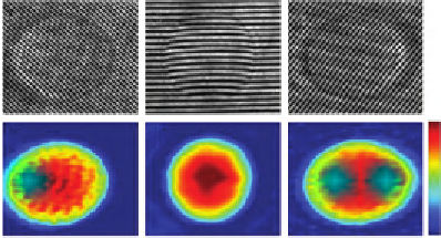
Figure 12.11
(A) Sample and reference beam geometry incident on image plane. k
R
is reference beam wave
vector and k
S
(
θ
) is sample beam wave vector. (B
D) Detail of raw images of a 10
μ
m polystyrene
bead for
θ
52
θ
max
, 0, and
θ
max
. Scale bar, 5
μ
m. (E
G) Corresponding phase images. Color bar,
phase in radians
[25]
.


Search WWH ::

Custom Search