Biomedical Engineering Reference
In-Depth Information
2
r
2
ω
2
P
ω
Iðr; zÞ
5
exp
2
(10.3)
2
ðzÞ
2
ðzÞ
where
P
is the power of the beam and
ω
is the beam radius at the axial distance
z
, given by:
"
#
1
=
2
2
λz
πω
ωðzÞ
5
ω
0
1
1
(10.4)
2
0
where
ω
0
is the minimum beam waist diameter.
Thus, the particle is trapped into the light beam by the gradient force
F
grad
and directed
along the optical axis due to the scattering force
F
scat
.
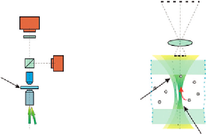
10.2.2 Experimental Setup
The optical configuration shown in
Figures 10.1 and 10.2
uses the same laser source to
drive particles into a chosen position and to record digital holograms simultaneously.
We present results using three types of micro-objects: 1) 9.7 micron latex microspheres, 2)
the preadipocyte mouse cell (3I3-F442A) undergoing differentiation, and 3) glutaraldehyde-
fixed bovine spermatozoa. Bovine spermatozoa were prepared by the Lazzaro Spallanzani
Institute, and fixed in suspension using 0.2% glutaraldehyde in PBS without calcium and
magnesium (1:3 v/v).
The latex spheres or cells were injected into a microfluidic chamber. The chamber
dimensions were 5 mm
3
35 mm
3
0.3 mm, and made of two cover glasses of 0.15 mm
thickness that were assembled together with a space made from double-sided sticky tape
(A)
(B)
H
CCD (H)
P
MO
CCD (I)
Sample
chamber
MO
Reference
beams
Laser
beams
Capture/object beam
Figure 10.1
(A) Optical configuration adopted; (B) the “in-axis” (or object) beam traps and drives the
particle, the “off-axis” (or reference) generates the hologram in the H plane.


Search WWH ::

Custom Search