Biomedical Engineering Reference
In-Depth Information
(A)
(B)
(C)
(D)
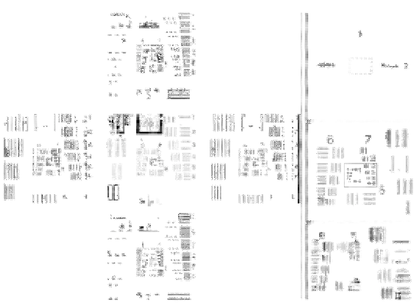
Figure 9.9
(A) Recovered bandpass images of the proposed SALDHM incoming from on-axis (central image)
and off-axis (four outer images) illuminations: (B) generated SA, (C) superresolved image, and (D)
magnified area of the inner part marked with a solid white line rectangle in case (C). The off-axis
illuminations are provided by the second illumination ring.
addition of a new rectangular pupil. This second illumination ring is produced by combining
two identical wedge prisms like in a beam steering application. With this procedure, a set of
tilted beams having an oblique illumination angle of 20
are produced over the input plane
defining our second illumination ring. The new set of bandpass images (outer images)
provided by the second illumination ring is included in
Figure 9.9A
, in addition again with the
one obtained using the on-axis illumination (inner image). The SA incoming from the addition
of the eight off-axis elementary apertures plus the on-axis one is presented in
Figure 9.9B
.And
finally, the superresolved image is included in
Figure 9.9C
while a magnification of its central
part is depicted in
Figure 9.9D
. We can see that the three last elements of the test target are
resolved in both H and V directions for the superresolved image.
According to the theory, the SNA and the superresolution limits in H and V directions are
given by SNA
HOR
5
0.45 and SNA
VER
5
0.42, and SR
HOR
5
1.41
μ
m (709 lp/mm) and

Search WWH ::

Custom Search