Biomedical Engineering Reference
In-Depth Information
(A)
(B)
(C)
(D)
(E)
5µm
5µm
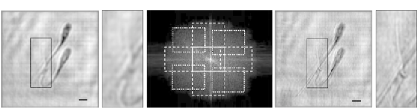
Figure 9.4
Imaging swine sperm cells using SALDHM: (A,B) the conventional low-resolution image and a
magnification area of the sperm's tail, respectively; (C) the generated SA incoming from the
addition of eight off-axis apertures plus the on-axis one and where the nine elementary apertures
are outlined with white lines for clarity. (D,E) The superresolved image and a magnification area
of the sperm's tail (the same one as in (B)), respectively.
sperm cells have an ellipsoidal head of 6
μ
m
3
9
μ
m and a tail's width of around 2
μ
mon
the head side and below 1
m on its end.
Figure 9.4
shows the experimental results. Now,
not only four off-axis elementary apertures are considered but eight ones as we can see in
the generated SA (
Figure 9.4C
). Thus, full 2D spatial-frequency space is covered in the
generated SA. We observe that the thinner part of the tail which is not visible under
conventional DIHM (
Figure 9.4A and B
) becomes resolved after applying the proposed
SALDHM approach (
Figure 9.4D and E
). In addition, we see in
Figure 9.4C
that the
elementary apertures in the V direction are quasi-contiguous with the central one, thus
satisfying the maximum expansion condition for the SA generation.
μ
9.3 SALDHM Outside the Gabor's Regime
When the sample is not weakly diffractive, an external reference beam must be added at the
recording plane to allow holographic recording. In this case, our proposed experimental
setup is depicted in
Figure 9.5A and B
for the on-axis and off-axis illumination cases,
respectively. It is based on a Mach-Zehnder interferometric configuration in which a
He
Ne laser beam is split in two branches. In the first one (imaging branch), the object
under test is illuminated in transmission mode and its diffracted Fresnel pattern recorded by
a CCD. This diffracted pattern is combined at the CCD plane with a second beam incoming
from the reference branch by using a beam splitter cube. The reference beam is an off-axis
spherical divergent wave front having the particularity that the distance “
d
” between the
object and the CCD (see
Figure 9.5
) is equal to the distance between the reference point
source (focal plane of the Fourier transforming lens in
Figure 9.5
) and the CCD. This
configuration defines a digital lensless Fourier transforming holographic setup where the
entire information about the complex diffracted wave front coming from the input object
Search WWH ::

Custom Search