Biomedical Engineering Reference
In-Depth Information
30
(A)
(B)
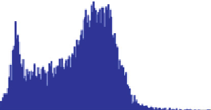
Average speed: 73.5
µ
m/s
20
10
1mm
0
Sperm trajectories over 10 s
(FOV ~24 mm
2
)
0
50
100
150
200
Speed (
µ
m/s)
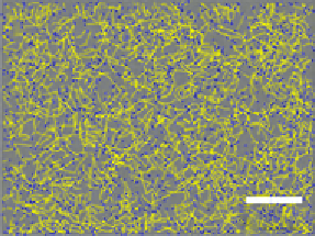
Figure 8.4
(A) Dynamic trajectories of 1831 motile sperms within an FOV of
24 mm
2
are automatically
B
10 s. The yellow lines illustrate the trajectories of the tracked
sperms, while the blue spots mark their end positions. (B) The sperm displacements from all the
consecutive frames in (A) are summed up and then divided by the total image acquisition
duration to provide the speed histogram.
tracked over a time span of
B
then be calculated through the magnitudes of these sperm displacements accumulated over
the total duration of the frame acquisition, as shown in
Figure 8.4B
.
8.5 High-Throughput On-Chip Semen Analysis Results
The imaging capabilities of partially coherent lensless on-chip holography toward
automated semen analysis can first be investigated through quantification of immobilized
sperm. In our experiments, both amplitude and phase images of sperm samples were
digitally reconstructed from their lensless holograms over an imaging FOV of
B
24 mm
2
,as
detailed in
Sections 8.3 and 8.4
[10].
Figure 8.2
shows a digitally focused region of this
FOV with raw lensless holograms of a few sperm and their corresponding reconstruction
results.
An interesting observation in these images is that, while the heads of the sperm can be
clearly observed in both the amplitude and the phase images, the sperm tails were only
visible in the reconstructed phase images (see
Figure 8.2B and C
). This is due to the fact
that a sperm's tail is a submicron structure which has a relatively weak scattering property.
Therefore, such a small structure cannot generate enough scattered field in the reconstructed
amplitude image with the limited NA and SNR of our wide-field lensless microscope
shown in
Figure 8.1
. However, a sufficient contrast in the reconstructed phase image can
still be created by the refractive index difference between the tail and the surrounding
medium, which permitted automated detection of the sperm tails shown in
Figure 8.2C and
D
with the procedures described in
Section 8.4
. Once identified, the sperm tails in


Search WWH ::

Custom Search