Biomedical Engineering Reference
In-Depth Information
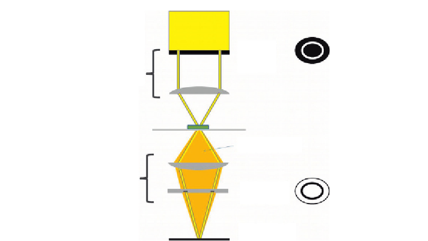
Annulus
Condenser
Deviated light
Objective
Phase plate
Image plane
Figure 1.6
Schematic diagram of the arrangement of a phase contrast microscope.
A light source giving homogeneous illumination is used. This is typically a halogen bulb or
LED providing K
¨
hler illumination of the sample. The light that passes straight through
without being diffracted (the zeroth order, undeviated, or reference waves) passes through
the phase plate in a specific region (the conjugate region). The light that is diffracted
changes angle and when collected by the objective passes through a different region of the
phase plate (the complementary region). The phase plate is of a different thickness in these
two regions and the difference in the optical path lengths (the product of refractive index
(
n
) and thickness) produces a phase shift between surround and diffracted waves of
λ
/4.
The undeviated light in
Figure 1.6
passes through a thinner region of the phase plate and is
advanced relative to the diffracted waves. This addition of a phase shift between the two
waves adds to the difference in phase shift produced by the sample to enable intensity
changes at the image plane through interference of the two waves.
The second function of the phase plate is to balance the intensity of the diffracted and
reference waves, again achieved by means of them being spatially separated and passing
through a different part of the phase plate. The unaltered reference wave passes through the
ring on the phase plate, which is typically made partially opaque with a neutral density
coating to attenuate this light to make it more comparable in amplitude to the diffracted
light. Typically, around 75% of the surround light is absorbed at the phase plate to provide
balance.
Search WWH ::

Custom Search