Hardware Reference
In-Depth Information
Finally, whilst timing is rarely a critical issue, some advantages can accrue
from placing cards in older ISA/EISA-based systems closer to the processor.
A particular case in point is the memory expansion cards that may be fitted to
older ISA/EISA systems. These should ideally be fitted in slot positions 6, 7,
and 8 in preference to positions 1, 2, and 3. In some cases this precaution could
be instrumental in improving overall memory access times and avoiding parity
errors. We continue this chapter by examining the ISA/EISA, PCI, and AGP
bus standards in greater detail.
Industry Standard
Architecture (ISA) bus
The original PC expansion bus supported an 8-bit data path (ISA) but the bus
was soon extended to support the full 16-bit bus (EISA). Despite the emergence
of PCI as an enhanced bus standard, many ISA and EISA cards are still in current
use in control and instrumentation systems, and are still available from a number
of suppliers.
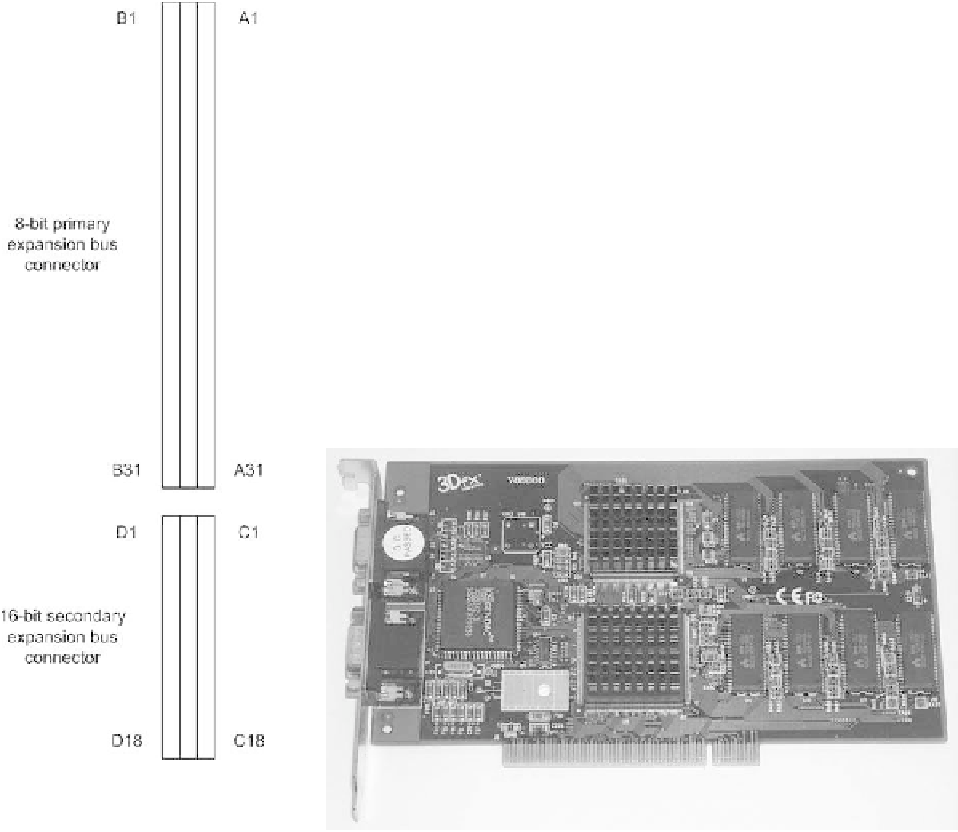
The 62-way ISA (PC expansion bus) connector
The 62-way ISA expansion bus connector was based on a number of direct
edge connectors fitted to the system motherboard. One side of the connector is
referred to as A (lines as numbered Al to A31) while the other is referred to as
B (lines are numbered B1 to B31). The address and data bus lines are grouped
together on the A-side of the connector while the control bus and power rails
occupy the B-side (see Figure 2.3).
It is, however, important to be aware that some early PC expansion bus pin-
numbering systems did not use letters A and B to distinguish the two sides of the
expansion bus connector. In such cases, odd-numbered lines (1 to 61) formed
one side of the connector whilst even-numbered lines (2 to 62) formed the
other. Here we shall, however, adopt the more commonly used pin-numbering
convention described earlier.
Figure 2.3
Pin numbering for
PC/PC-AT ISA and EISA
expansion cards (viewed
from above)
Photo 2.6
A PCI 3D graphics adapter card