Hardware Reference
In-Depth Information
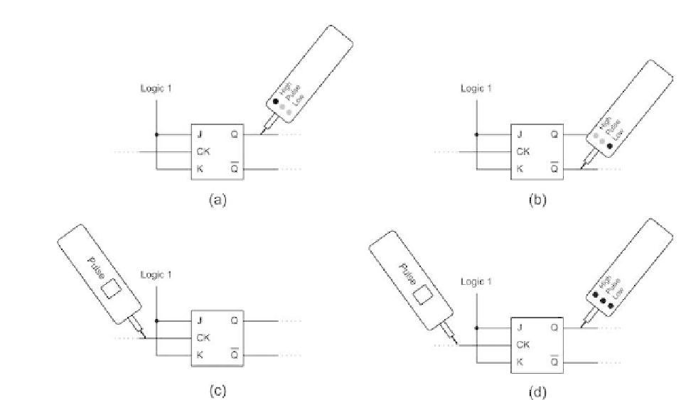
Figure 13.24
Using a logic pulser and logic probe to check the operation of a
J-K bistable. The pulser is used to force a change of logic level at the clock
(CK) input of the bistable
Oscilloscopes
The use of an oscilloscope in the examination of time-related signals (wave-
forms) is well known. Such instruments provide an alternative means of tracing
logic states present in a PC-based system and may also be used for detecting
noise and unwanted AC signals which may be present on power-supply rails.
It must, however, be stressed that, since low-cost oscilloscopes generally do
not possess any means of storing incoming signals, severe triggering problems
arise when signals are non-repetitive. This is an important point since many of
the digital signals present on a bus are both asynchronous and non-repetitive.
Apart from displaying the shape of waveforms present in a bus system, oscil-
loscopes can also be used to make reasonably accurate measurements of voltage
and time. In such cases, measurements are made with reference to a graticule
fitted to the CRT and scale factors are applied using the time and voltage range
switches. However, before attempting to take measurement from the graticule it
is essential to check that any variable front panel controls are set to the calibrate
(CAL) position. Failure to observe this simple precaution may result in readings
which are at best misleading or at worst grossly inaccurate.
Since modern oscilloscopes employ DC coupling throughout the vertical
amplifier stages, a shift along the vertical axis will occur whenever a direct volt-
age is present at the input. When investigating waveforms in a circuit one often
encounters AC signals superimposed on DC levels; the latter may be removed
by inserting a capacitor in series with the input using the 'AC-GND-DC'